
Motor cooling method for a compressor

Active Publication Date: 2015-08-13
JOHNSON CONTROLS TYCO IP HLDG LLP
View PDF4 Cites 9 Cited by
  • Summary
  • Abstract
  • Description
  • Claims
  • Application Information

AI Technical Summary

Benefits of technology

The patent text describes a system that uses liquid refrigerant to cool the stator and electromagnetic bearings of a motor. The refrigerant circulates through a gap between the motor housing and a spacer, which is made of a highly conductive material. The spacer prevents leakage of the refrigerant and also cools the stator. A pin through the housing prevents movement of the stator and damage to the rotation and axial motion. The technical effect is greater energy efficiency and better cooling of the motor.

Problems solved by technology

Such leakage may reduce the energy efficiency of the compressor.

Method used


Image

  • Motor cooling method for a compressor
  • Motor cooling method for a compressor
  • Motor cooling method for a compressor

Examples


Embodiment Construction

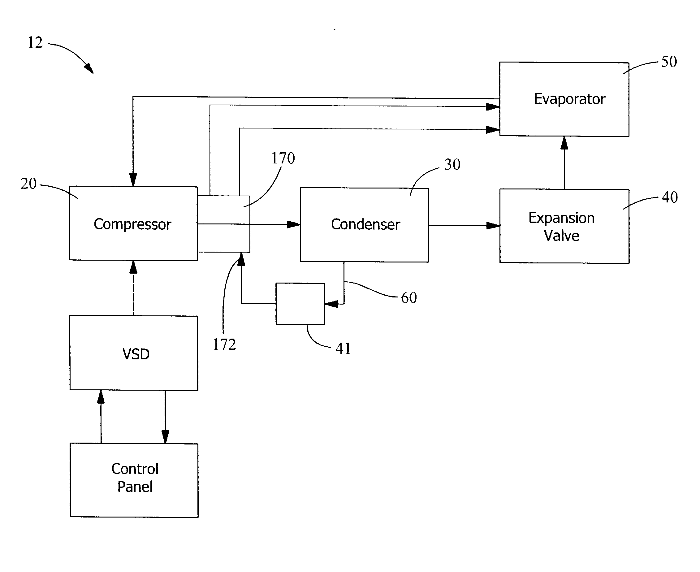
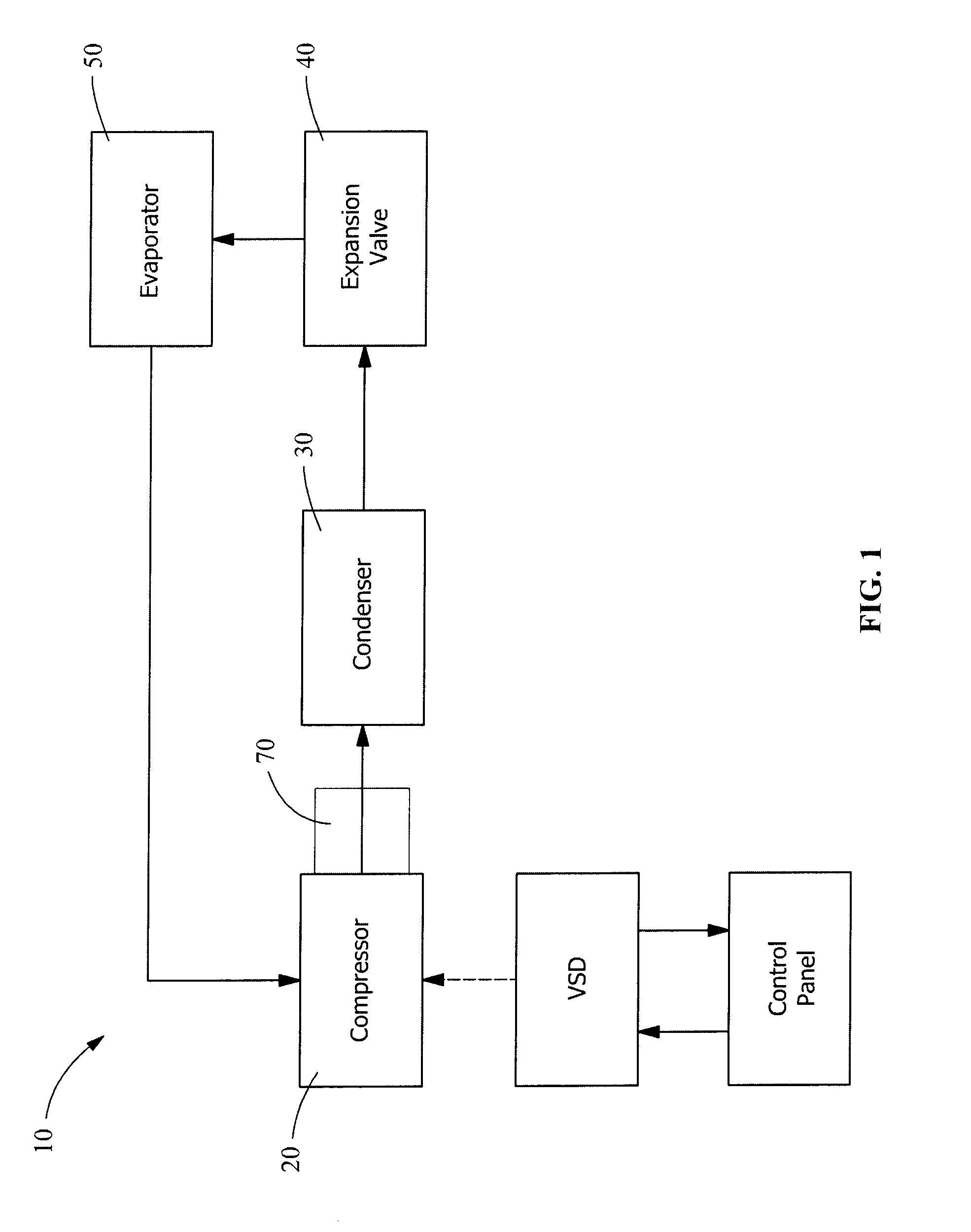
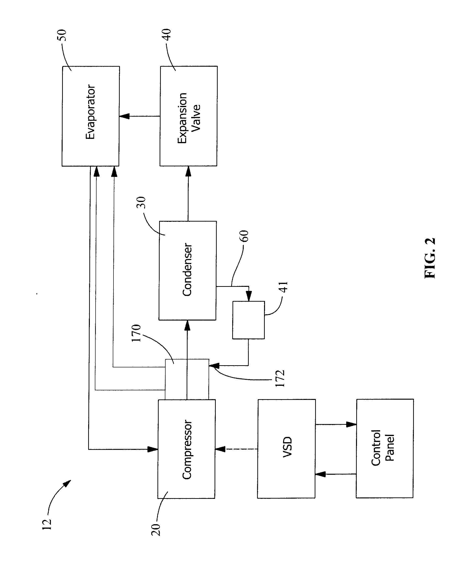
[0020]The refrigerant circuit of the present invention differs in some regards from a standard refrigerant circuit. FIG. 1 is a schematic of a well known refrigerant circuit 10. The flow of refrigerant in the refrigeration circuit is shown by solid lines. Also shown in FIG. 1 are the electrical connection between the variable speed drive (VSD) and motor 170, and the draw of power from the VSD to motor 170, represented by a dashed line, to distinguish the electrical circuits from the refrigeration circuits. As shown, the VSD is in communication with the control panel. The control panel, not shown in FIG. 1 but shown schematically in FIG. 3, is also in communication with the refrigeration system. High pressure refrigerant from the compressor 20 is discharged through compressor discharge port which is in fluid communication with a condenser 30 that condenses the high pressure refrigerant gas into a hot pressurized liquid. Condenser 30 is in heat exchange communication with a first heat...


PUM


Abstract

A method for cooling a compressor motor (170) and a cooling circuit utilizing refrigerant that originates in the condenser (30) to cool a motor (170) and electromagnetic bearings (196, 206). The motor drives a compressor (20), while the electromagnetic bearings support the motor rotor (178) during operation of the compressor. Liquid refrigerant from the condenser is expanded into a two-phase mixture, passed over the stator, expanded a second time, passed over the bearings and between the stator and rotor, before being returned to an evaporator (50).

Description

FIELD OF THE INVENTION[0001]The present invention is generally directed to motor cooling. And specifically directed to motor cooling scheme for a compressor.BACKGROUND OF THE INVENTION[0002]A well-known refrigeration cycle is a closed loop system in which refrigerant, the working fluid, is compressed by a compressor that increases the pressure of the refrigerant gas. The compressor is driven by a motor that is controlled by a control panel. High pressure refrigerant from the compressor is discharged through the compressor discharge which is in fluid communication with a condenser that condenses the high pressure gas into a pressurized fluid. In one embodiment, the compressor is a centrifugal compressor. Alternatively, the compressor may be a reciprocating, rotary, scroll, or screw compressor.[0003]The condenser is in heat exchange communication with a first heat transfer medium that removes heat of condensation from the refrigerant, resulting from the change of state of refrigerant ...

Claims


Application Information

Patent Timeline
IPC IPC(8): F25B31/00H02K11/00H02K5/20H02K7/09H02K9/10H02K9/20
CPCF25B31/008H02K9/10H02K11/00H02K5/20H02K7/09H02K9/20F04D29/058F04D29/5806F04D25/06F04D29/584F16C37/005H02K5/203
Inventor SOMMER, STEVEN T.SCHREIBER, JEB W.ESTES, STEVEN J.
Owner JOHNSON CONTROLS TYCO IP HLDG LLP
Learn More