Process for Separating Hydrogen from an Olefin Hydrocarbon Effluent Vapor Stream

Active Publication Date: 2019-05-09
ENFLEX INC
View PDF2 Cites 2 Cited by
  • Summary
  • Abstract
  • Description
  • Claims
  • Application Information

AI Technical Summary

Benefits of technology

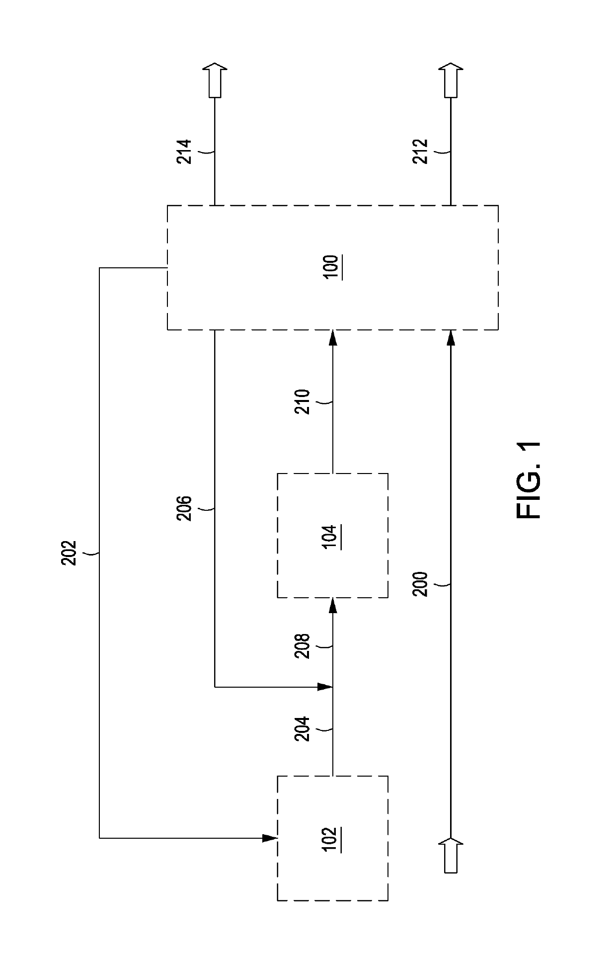
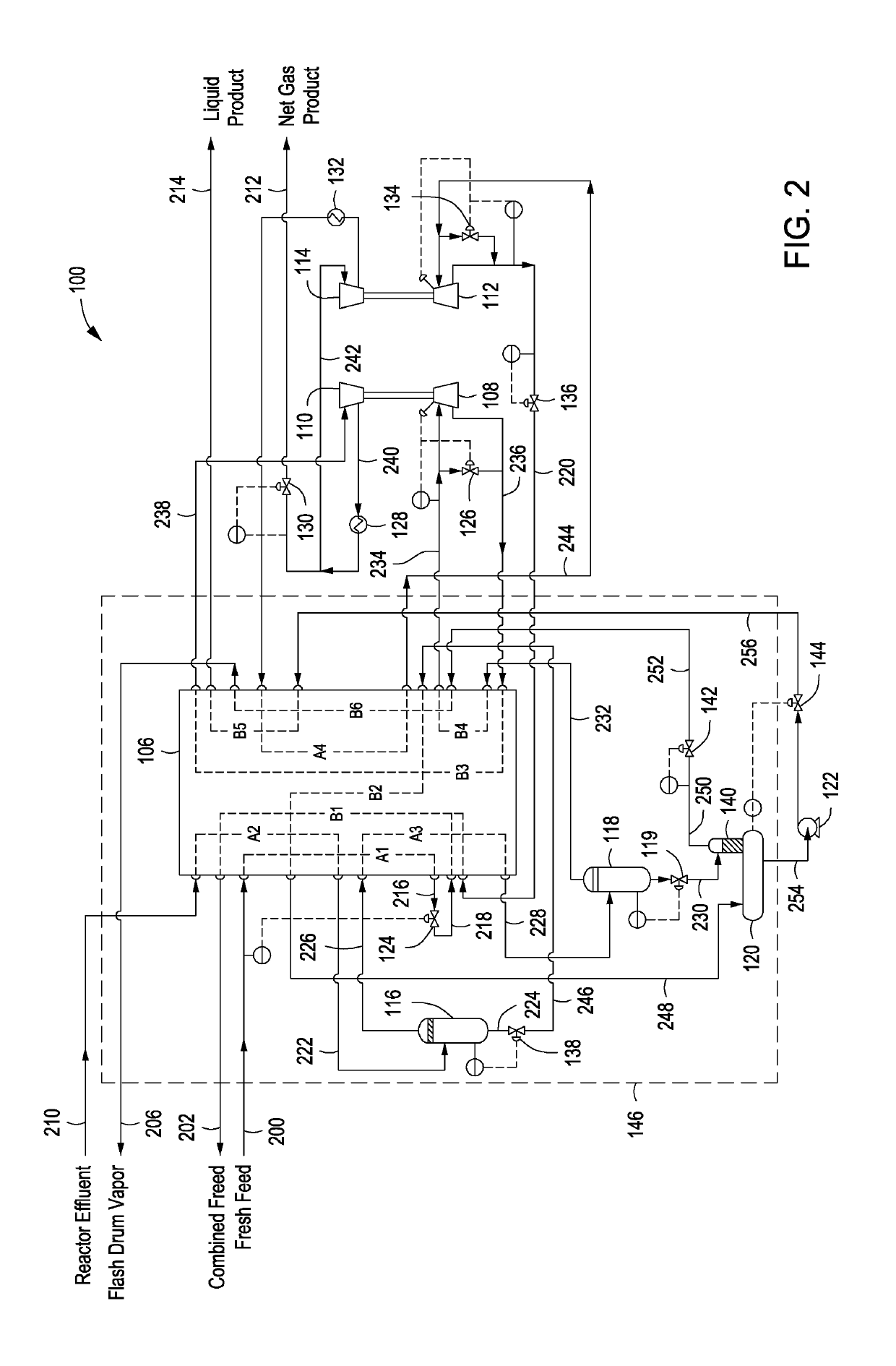
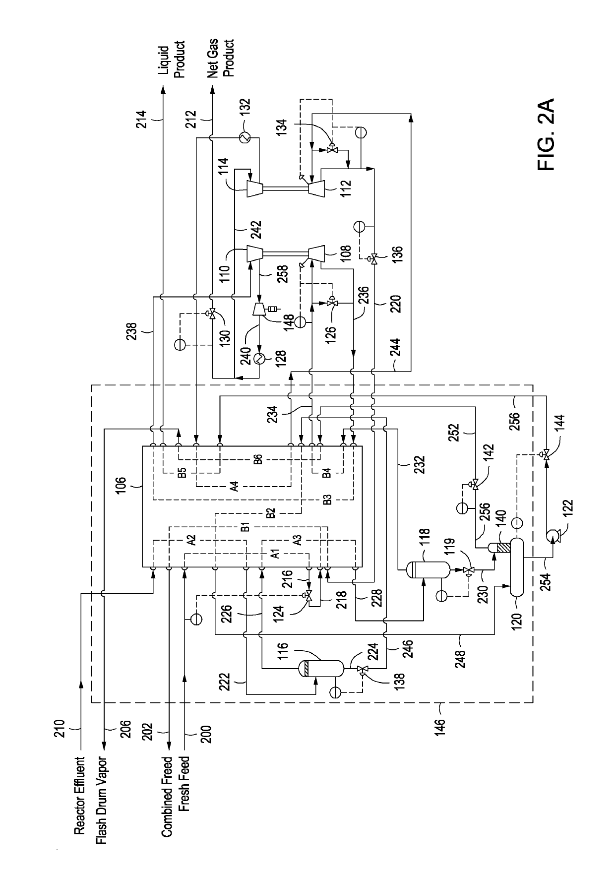
[0005]One or more specific embodiments disclosed herein includes a process for the separation of hydrogen from an olefin hydrocarbon rich compressed effluent vapor stream from a dehydrogenation unit, comprising cooling a compressed effluent vapor stream in a heat exchanger; separating hydrogen from olefin and heavy paraffinic components in the cooled compressed effluent vapor stream in a first separator to provide a first vapor stream and a first liquid stream; cooling the first vapor stream in the heat exchanger; separating hydrogen from olefin and heavy paraffinic components in the cooled first vapor stream in a second separator to provide a second vapor stream and a second liquid stream; warming the second vapor stream in the heat exchanger; isentropically expanding, in a high-pressure expander, the second vapor stream, wherein the pressure and temperature of the second vapor stream are lowered; warming the second vapor stream in the heat exchanger; compressing, in a high-pressure compressor, the second vapor stream; cooling the second vapor stream in a first discharge cooler; dividing the second vapor stream into a gas product and a split stream; withdrawing the gas product; compressing, in a low-pressure compressor, the split stream; cooling the split stream in a second discharge cooler and further cooling the split stream in the heat exchanger; isentropically expanding, in a low-pressure expander, the split stream, wherein the pressure and temperature of the split stream are lowered; cooling a liquid paraffinic stream in the heat exchanger; combining the cooled liquid paraffinic stream with the expanded split stream to provide a combined feed; vaporizing the combined feed in the heat exchanger; withdrawing the vaporized combined feed; lowering the pressure of the first liquid stream in a control valve; partially vaporizing the first liquid stream in the heat exchanger; flashing the partially vaporized first liquid stream in a liquid product drum to provide a hydrogen-rich gas, which travels to a rectifier connected to the liquid product drum; combining the hydrogen-rich gas and the second liquid stream in the

Problems solved by technology

However, those processes and systems lack all the steps or feature

Method used


Image

  • Process for Separating Hydrogen from an Olefin Hydrocarbon Effluent Vapor Stream
  • Process for Separating Hydrogen from an Olefin Hydrocarbon Effluent Vapor Stream
  • Process for Separating Hydrogen from an Olefin Hydrocarbon Effluent Vapor Stream

Examples


Example

1. Introduction

[0021]A detailed description will now be provided. The purpose of this detailed description, which includes the drawings, is to satisfy the statutory requirements of 35 U.S.C. § 112. For example, the detailed description includes a description of the inventions defined by the claims and sufficient information that would enable a person having ordinary skill in the art to make and use the inventions. In the figures, like elements are generally indicated by like reference numerals regardless of the view or figure in which the elements appear. The figures are intended to assist the description and to provide a visual representation of certain aspects of the subject matter described herein. The figures are not all necessarily drawn to scale, nor do they show all the structural details of the systems, nor do they limit the scope of the claims.

[0022]Each of the appended claims defines a separate invention which, for infringement purposes, is recognized as including equivale...


PUM


Abstract

One or more specific embodiments disclosed herein includes a method for separating hydrogen from an olefin hydrocarbon rich compressed effluent vapor stream, employing a single heat exchanger, multiple gas-liquid separators, multiple expander/compressor sets, and a rectifier attached to a liquid product drum.

Description

CROSS-REFERENCE TO RELATED APPLICATIONS[0001]This application is a continuation-in-part of U.S. application Ser. No. 15 / 600,758 filed on May 21, 2017, which is herein incorporated by reference in its entirety.STATEMENT REGARDING FEDERALLY SPONSORED RESEARCH OR DEVELOPMENT[0002]Not applicable.BACKGROUND1. Field of Inventions[0003]The field of this application and any resulting patent is processes and systems for separating hydrogen from an olefin hydrocarbon vapor stream.2. Description of Related Art[0004]Various processes and systems have been proposed and utilized for separating hydrogen from an olefin hydrogen rich compressed effluent vapor stream, including some of the processes and systems disclosed in the references appearing on the face of this patent. However, those processes and systems lack all the steps or features of the processes and systems covered by any patent claims below. As will be apparent to a person of ordinary skill in the art, any processes and systems covered...

Claims


Application Information

Patent Timeline
IPC IPC(8): F25J3/02
CPCF25J3/0252F25J3/0219F25J2200/02F25J2205/04F25J2215/10F25J2230/60F25J2230/08F25J2240/04F25J2240/40F25J2270/06F25J2230/20F25J2210/12F25J2210/62F25J2215/02F25J2215/04F25J2215/64F25J2230/30F25J2230/32F25J2235/60F25J2245/02F25J2270/904F25J3/0242F25J3/0238F25J2210/04F25J3/062F25J3/0655F25J3/0645
Inventor ZHAO, JAMESZHAO, SHUKUI
Owner ENFLEX INC
Why Eureka
Try Eureka