Sound processing apparatus and sound processing method

a sound processing apparatus and sound processing technology, applied in direction finders, direction finders using ultrasonic/sonic/infrasonic waves, direction finders, etc., can solve the problems of not being able to acquire transfer functions in desired sound source directions, and the inability to estimate transfer functions in individual rooms, so as to reduce the possibility of localization, reduce the amount of data processed, and improve the reliability of calculated second transfer functions.

Active Publication Date: 2015-08-13
HONDA MOTOR CO LTD
View PDF9 Cites 50 Cited by
  • Summary
  • Abstract
  • Description
  • Claims
  • Application Information

AI Technical Summary

Benefits of technology

[0027]According to the configuration of (6), the second transfer function is calculated by interpolating the first transfer function in the sound source direction through the use of weighting based on the amount of sound source state information updated which is used to calculate the sound source direction. Since the reliability of the sound source direction calculated by the sound source direction calculating unit depends on the amount of sound source state information updated, it is possible to improve the reliability of the calculated second transfer function.
[0028]According to the configuration of (7), since the sound source state information is updated on the basis of the sound source direction which is information different from the time difference,...

Problems solved by technology

Transfer functions can be estimated using a geometric model from the positional relationships between the microphones and the sound sources which have been estimated using the sound source position estimating method described in Japanese Unexamined Patent Application, First Publication No. 2012-16...

Method used


Image

  • Sound processing apparatus and sound processing method
  • Sound processing apparatus and sound processing method
  • Sound processing apparatus and sound processing method

Examples


first embodiment

[0052]Hereinafter, a first embodiment of the present invention will be described with reference to the accompanying drawings.

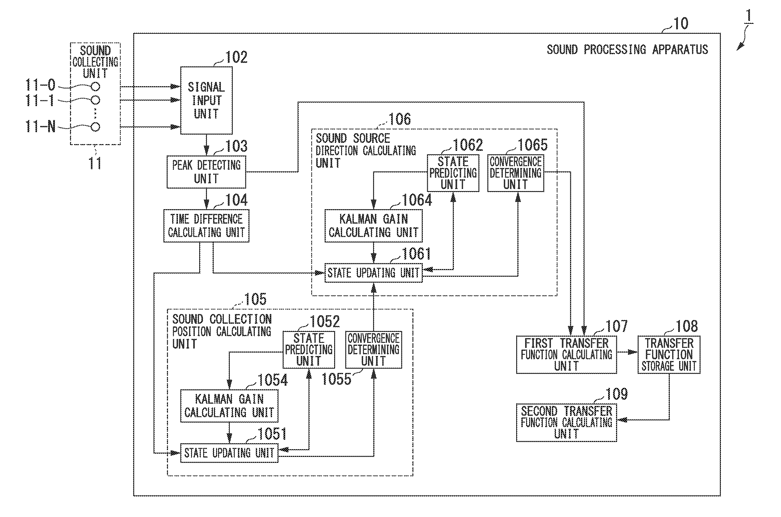
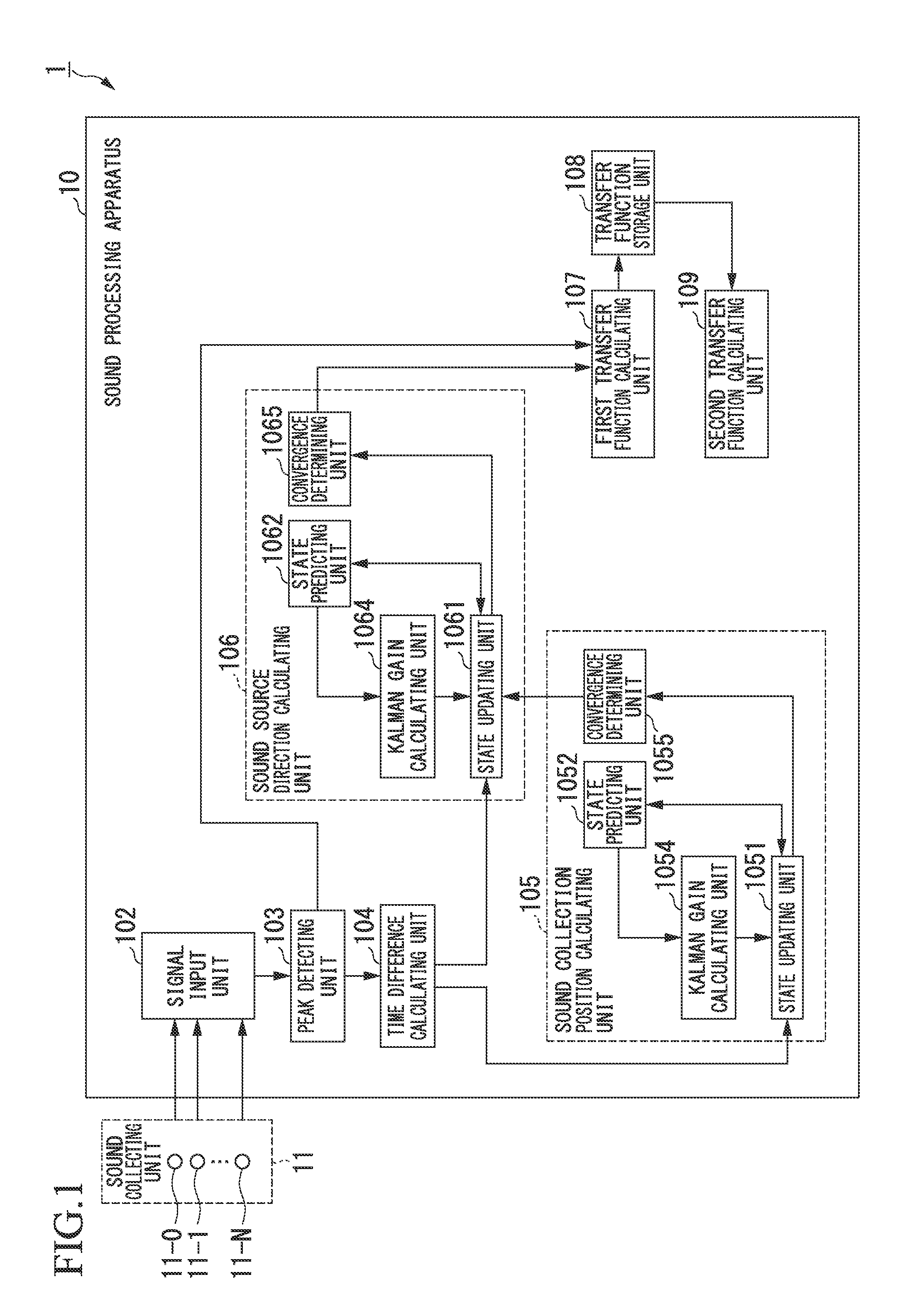
[0053]FIG. 1 is a block diagram schematically illustrating a configuration of a sound processing system 1 according to this embodiment.

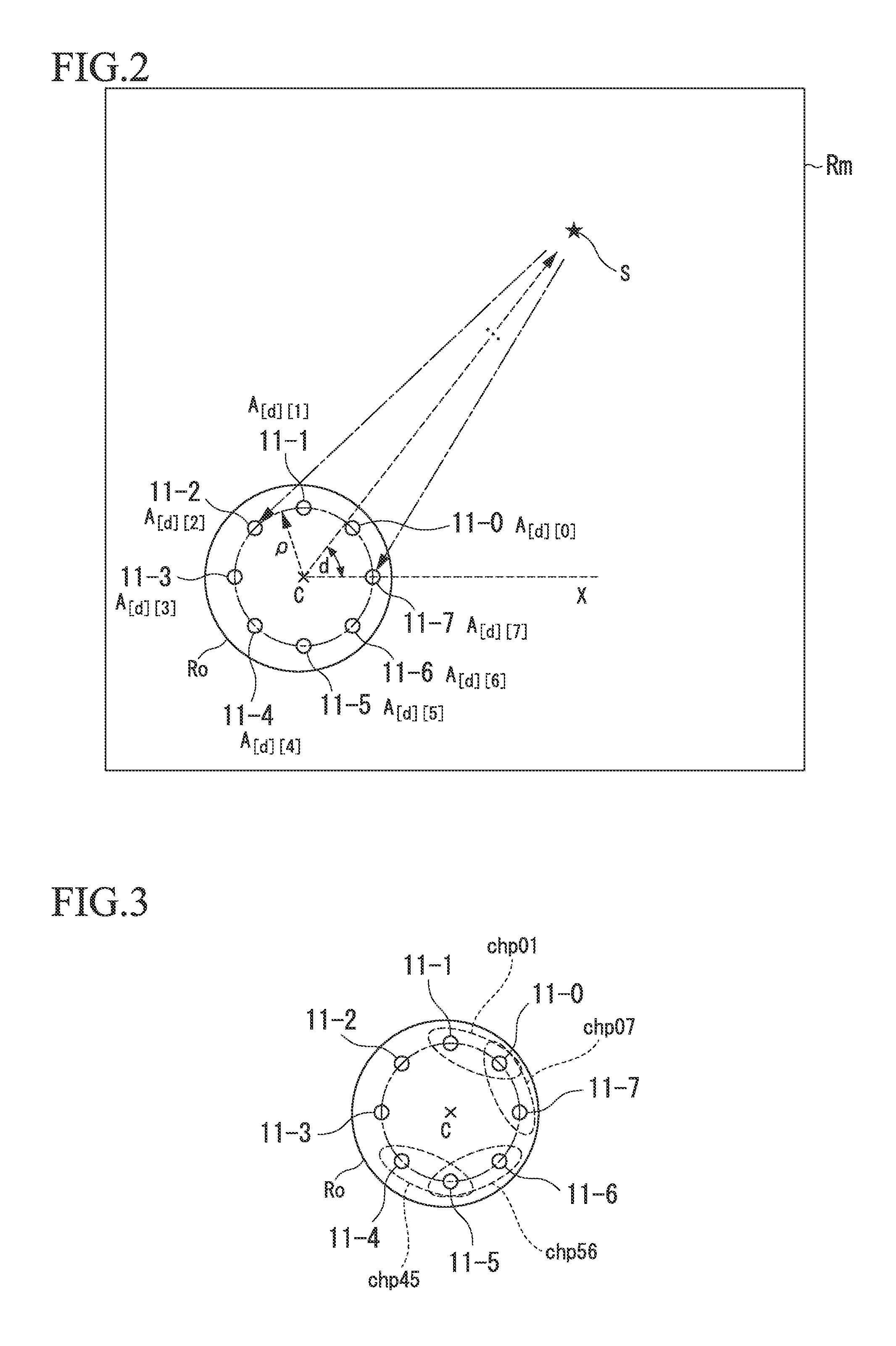
[0054]The sound processing system 1 includes a sound processing apparatus 10 and N+1 (where N is an integer greater than 1) sound collecting units 11-0 to 11-N. In the following description, each or all of the N+1 sound collecting units 11-0 to 11-N may be collectively simply referred to as sound collecting unit 11. Each sound collecting unit 11-n (where n is an integer from 0 to N) is a microphone. The sound collecting unit 11-n outputs a collected sound signal to the sound processing apparatus 10. Accordingly, the sound collecting unit 11 outputs sound signals of N+1 channels based on sound arriving as a whole to the sound processing apparatus 10.

[0055]The sound processing apparatus 10 includes a signal input unit 102, a peak...

second embodiment

[0190]A second embodiment of the present invention will be described below with reference to the accompanying drawings. The same elements as in the aforementioned embodiment will be referenced by the same reference numerals and a description thereof will not be repeated.

[0191]FIG. 11 is a block diagram schematically illustrating a configuration of a sound processing system 1A according to this embodiment.

[0192]The sound processing system 1A includes a sound collecting unit 11 and a sound processing apparatus 10A.

[0193]The sound processing apparatus 10A includes a signal input unit 102, a peak detecting unit 103, a time difference calculating unit 104, a sound collection position calculating unit 105, a sound source direction calculating unit 106A, a first transfer function calculating unit 107A, a transfer function storage unit 108, and a second transfer function calculating unit 109.

[0194]That is, the sound processing apparatus 10A includes the sound source direction calculating un...

third embodiment

[0205]A third embodiment of the present invention will be described below with reference to the accompanying drawings. The same elements as in the aforementioned embodiment will be referenced by the same reference numerals and a description thereof will not be repeated.

[0206]FIG. 13 is a block diagram schematically illustrating a configuration of a sound processing system 1B according to this embodiment.

[0207]The sound processing system 1B includes a sound collecting unit 11 and a sound processing apparatus 10B.

[0208]The sound processing apparatus 10B includes a signal input unit 102, a peak detecting unit 103, a time difference calculating unit 104, a sound collection position calculating unit 105, a sound source direction calculating unit 106B, a first transfer function calculating unit 107A, a transfer function storage unit 108, and a second transfer function calculating unit 109B.

[0209]That is, the sound processing apparatus 10B includes the sound source direction calculating un...


PUM


Abstract

A sound processing apparatus includes a sound collection position calculating unit configured to calculate sound collection positions of sound signals of multiple channels on the basis of the sound signals, a sound source direction calculating unit configured to calculate a sound source direction on the basis of the sound signals of multiple channels, a first transfer function calculating unit configured to calculate a first transfer function corresponding to the sound source direction on the basis of the sound signals of multiple channels, and a second transfer function calculating unit configured to calculate a second transfer function by interpolating the first transfer function corresponding to each of a plurality of sound source directions.

Description

CROSS REFERENCE TO RELATED APPLICATIONS[0001]Priority is claimed on Japanese Patent Application No. 2014-025757, filed on Feb. 13, 2014, the content of which is incorporated herein by reference.BACKGROUND OF THE INVENTION[0002]1. Field of the Invention[0003]The present invention relates to a sound processing apparatus and a sound processing method.[0004]2. Description of Related Art[0005]A transfer function indicating transfer characteristics when sound generated from a sound source propagates to a sound collecting unit might be used to process a collected sound signal. The transfer function is used for the purpose of correction of sound quality (such as equalizing), reverberation reduction, noise reduction, estimation of a sound source direction or a sound source position, and the like.[0006]Accordingly, various methods of calculating a transfer function have been proposed in the related art.[0007]For example, a sound system described in Japanese Patent No. 4482247 sequentially out...

Claims


Application Information

Patent Timeline
IPC IPC(8): G01S3/80
CPCG01S3/8006G01S3/801G01S3/808G01S5/20
Inventor NAKAMURA, KEISUKENAKADAI, KAZUHIROAMBROSE, SURYA
Owner HONDA MOTOR CO LTD
Why Eureka
Try Eureka