Method For Optimizing An Operating Function Of A Ground Milling Machine And Ground Milling Machine

a ground milling machine and operating function technology, applied in the direction of electric digital data processing, instruments, constructions, etc., can solve the problems of inability to achieve milling performance per fuel consumption, comparatively high operating costs of such ground milling machines, etc., to achieve uniform milling operation, reduce operating costs, and reduce operating costs

Active Publication Date: 2015-08-13
BOMAG
View PDF22 Cites 28 Cited by
  • Summary
  • Abstract
  • Description
  • Claims
  • Application Information

AI Technical Summary

Benefits of technology

[0012]It is fundamentally possible that the variation of the variable operating parameter, for example, the rotational speed, is performed continuously. According to the above-described preferred embodiment, in this way, in particular, with homogeneous ground conditions, optimal maximum advance velocities can be achieved. The ground subsoils to be processed are frequently comparatively heterogeneous, however, for example, with regard to their ground density and hardness of the ground materials to be milled. As a result, the optimum rotational speed for obtaining the at least theoretically maximum advance velocity varies in a specific range. To nonetheless enable comparatively continuous milling operation of the ground milling machine, it is therefore preferable if the variation of the rotational speed according to step d) is performed at fixed rotational speed intervals. In other words, this means that the variation of the rotational speed is performed in steps, for example, in steps of plus or minus ten revolutions per minute. The graduation of the variation steps is also dependent in this case, in particular, on the diameter of the milling drum. By way of a stepwise change of the rotational speed in milling operation, a comparatively coarser result is obtained with respect to the maximum achievable advance velocity. However, in this way the overall process of steps a) to f) can be substantially shortened. In summary, this means that the operating parameter, depending on the specific embodiment of the present invention, can be varied either continuously or also at fixed intervals.
[0013]For practical use, it has further proven to be advantageous if the checking according to step e) is performed in such a manner that exceeding or falling below difference threshold values is checked. The core element of this preferred refinement is, therefore, that a decrease or increase of the operating function to be optimized, for example, the advance velocity, is only assumed to be present if a minimum amount of velocity change is present. This amount, which is referred to as a difference threshold, for example, in the magnitude of ±1 km / h, is also used for the purpose of enabling more uniform milling operation under optimized operating conditions and therefore to make the responsiveness of the present present invention slower. It is thus ensured that not every minimal change of the advance velocity results in a change of the rotational speed of the milling drum, but rather this procedure is only triggered when the changes of the advance velocity exceed the predefined difference threshold values.
[0014]Depending on the application, it can furthermore be advantageous if the above-described method according to steps a) to f) is only carried out at the beginning of the milling operation and after reaching a termination criterion, for example, reaching the maximum advance velocity in step f) for the first time, the milling operation is continued with the value of the variable operating parameter then ascertained. In this method, the above-described optimization process is only carried out again in the event of a change of the operating parameters which are constant with regard to the optimization method, for example, the milling depth, and / or with the beginning of a new milling process. Alternatively, however, it can also be preferable if steps a) to f) are continued continuously over the entire milling process. In this refinement of the method according to the present invention, an adaptation of the operating parameter of the milling drum, therefore, takes place continuously, to achieve the respective operating optimum of the ground milling machine as much as possible over the entire milling process. Finally, it is also possible that the optimization process according to the present invention is carried out over the respective operating interval at regular time intervals and / or according to established milling distance intervals covered.
[0015]In the specific exemplary embodiment, the variation of the rotational speed of the milling drum can be achieved in various ways. In the simplest case, for example, the starting rotational speed of the drive unit, for example, an internal combustion engine, can be varied. However, this procedure is disadvantageous in that the operation of the main drive unit in a comparatively constant and energetically optimum operating range is always desired. Furthermore, transmissions can principally be integrated in the drive train, for example, shift transmissions, so that continuous rotational speed variability of the milling drum is not provided. The variation of the rotational speed is then performed in accordance with the shift stages of the shift transmission. However, it is particularly preferable if the variation of the rotational speed according to step d) of the milling drum is performed at least partially via a summation transmission, in particular, a planetary transmission, by variation of at least one input rotational speed of one of at least two drive units. Such an arrangement is specified, for example, in the patent family of DE 10 2012 006 189.7, to which reference is made, in particular, in this regard. Accordingly, a total of two drive units are provided for the rotational drive of the milling drum, wherein the main drive unit runs at a comparatively constant power level. The rotational speed variation is performed mainly via the second drive unit, which can be, in particular, a lower-power auxiliary drive, in particular, an electric motor or hydraulic motor. The drive powers introduced via the two drive units are subsequently combined via the summation transmission and transmitted to the milling drum via an output shaft, which is connected to the milling drum.
[0016]It is fundamentally possible to carry out the above-described method manually. Units are preferably provided for this purpose, for example, corresponding display screens, via which the operator of the ground milling machine can observe the effects of the variation of the value of the variable operating parameter, for example, the rotational speed, on the operating function to be optimized, for example, the advance velocity. However, it is preferable if the method according to the present invention is executed in the framework of an automatic controller. Automatic controller means in this case that, in particular, the steps a) to f) and, if present, the method steps of the preferred refinements, are executed in a computer-assisted manner and without manual influence, i.e., automatically. The operator of the ground milling machine must then only activate or deactivate this operating mode, without subsequently having to take care of a further regulation of the adaptation process between variable operating parameter and operating function to be optimized. A corresponding control unit is provided for this purpose.
[0017]A further essential aspect of the present invention is furthermore a ground milling machine for milling off ground subsoil material, in particular, a ground milling machine for carrying out the method according to the present invention. Generic ground milling machines comprise a machine frame, travel units connected to the machine frame, such as, in particular, crawler tracks and / or wheels, a drive unit, such as an internal combustion engine, in particular, and a milling drum. The milling drum has, in addition to a hollow cylindrical support tube, a plurality of chisel units arranged on the outer lateral surface of the support tube, as are already described in the prior art. The milling drum is mounted directly or indirectly on the machine frame so it is rotatable about a horizontal axis of rotation extending transversely to the working direction. Furthermore, a drive train is provided, which transmits drive energy from the drive unit to the milling drum. This drive train can comprise multiple transmission steps, for example, a shift transmission and / or a belt transmission or chain gear, etc. Furthermore, the ground milling machine has a unit for ascertaining and monitoring an operating function to be optimized, for example, the advance velocity. This unit is implemented such that it either can directly measure the value of the operating function to be optimized (for example, the advance velocity of the ground milling machine), or can measure a physical variable, which has a known relationship to the operating function to be optimized (for example, the rotational speed of the travel units). Such a unit can comprise, for example, a unit for measuring the advance velocity, i.e., for example, a rotational speed sensor on one of the travel units of the ground milling machine or also another unit, via which the travel velocity of the ground milling machine can be ascertained, for example, also on the basis of the ground subsoil. Depending on the specific operating function to be optimized, the unit for ascertaining and monitoring the operating function to be optimized can also comprise, for example, a sensor for the fuel consumption of the drive unit (for example, via measurement of the rotational speed of the drive motor). The unit for ascertaining and monitoring the operating function to be optimized can also comprise a data processing unit, which is suitable for the purpose of combining various signals recorded by sensors with one another, to calculate the operating function to be optimized therefrom, for example, by multiplying the ascertained advance velocity of the ground milling machine with the set milling depth and dividing by the ascertained fuel consumption of the ground milling machine, to ascertain the milling performance efficiency of the ground milling machine.

Problems solved by technology

The operation of such ground milling machines is comparatively costly, so that the demand always exists for the most optimum possible machine operation, for example, with respect to the lowest possible fuel consumption and, at the same time, the highest possible milling performance.
In practical use of such machines, it has been shown that various operating optima, for example, the optimum of the milling performance, i.e., the milling volume per unit of time, for example, in cubic meters per hour, and also the optimum of the milling performance efficiency, i.e., the milling performance per fuel consumption, are not always achieved with higher rotational speed of the milling drum.

Method used


Image

  • Method For Optimizing An Operating Function Of A Ground Milling Machine And Ground Milling Machine
  • Method For Optimizing An Operating Function Of A Ground Milling Machine And Ground Milling Machine
  • Method For Optimizing An Operating Function Of A Ground Milling Machine And Ground Milling Machine

Examples


Embodiment Construction

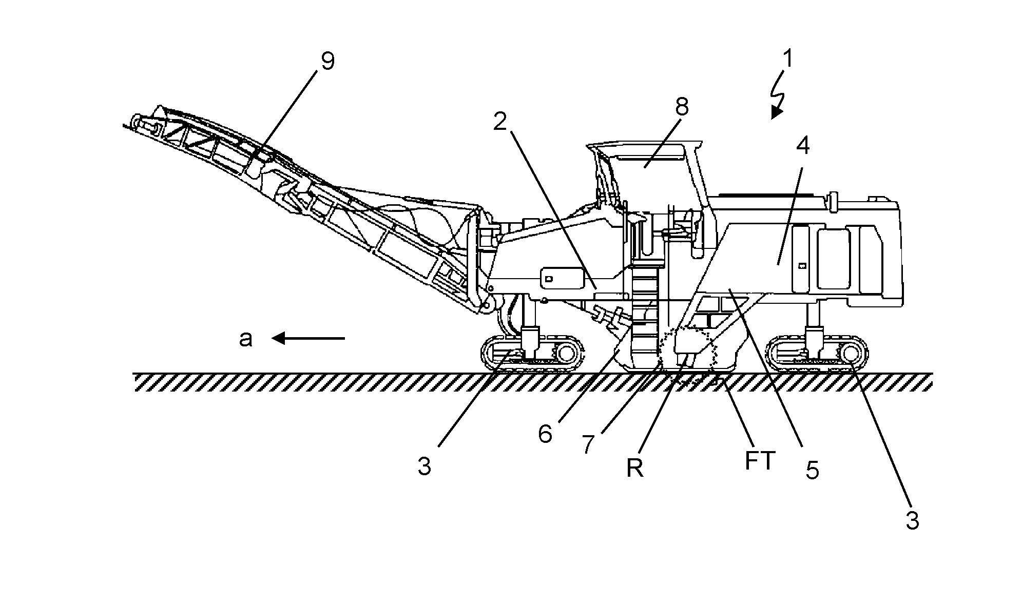
[0033]Essential elements of the ground milling machine 1, which is implemented as a road milling machine of the middle rotor milling machine type, shown in FIG. 1 are, in particular, a machine frame 2, travel units 3, and a main drive unit 4 not indicated in greater detail, which is connected to a milling drum 7 arranged in a milling drum box 6 via a drive train 5. Furthermore, a driver's cab 8 and a conveyor belt 9 are provided, via which milled material can be transported away from the ground milling machine 1. In work operation, the ground milling machine 1 travels, with the milling drum 7 lowered into the ground subsoil at the milling depth FT, in the working direction a over the ground subsoil, milling off ground subsoil material to the desired depth at the same time.

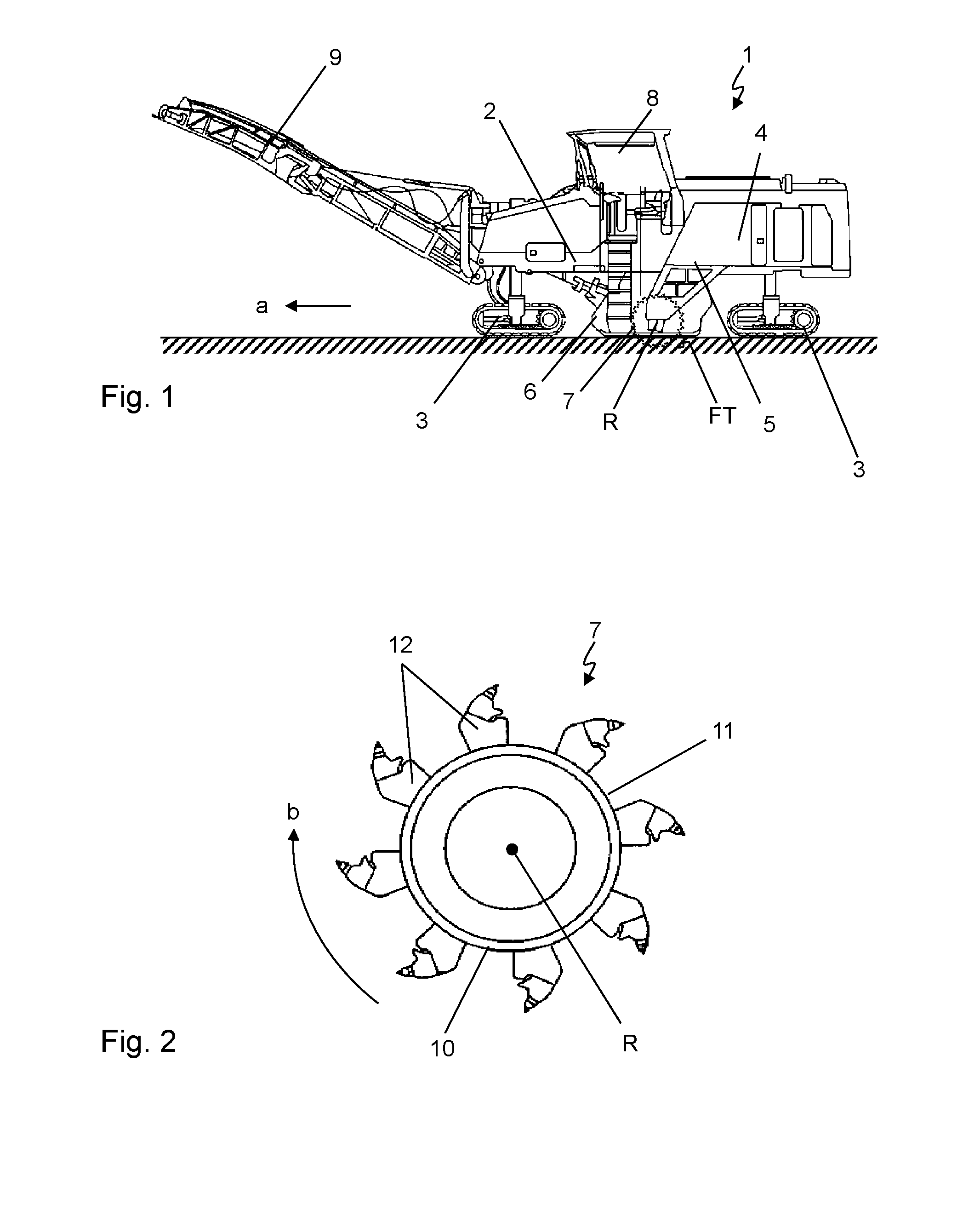
[0034]The essential element of the milling drum 7, which is only indicated very schematically in FIG. 1, is a hollow-cylindrical support tube 10, on the outer jacket surface 11 of which a plurality of milling tools...


PUM


Abstract

The present invention relates to a method for optimizing an operating function of a ground milling machine by way of the adaptation of operating parameters and to a ground milling machine which is implemented, in particular, for carrying out this method. In an essential aspect an operating parameter of a milling machine is provided starting from a starting value of the operating parameter to optimize an operating function of the ground milling machine in milling operation.

Description

CROSS-REFERENCE TO RELATED APPLICATIONS[0001]The present application claims priority under 35 U.S.C. §119 of German Patent Application No. 10 2014 001 885.7, filed Feb. 12, 2014, the disclosure of which is hereby incorporated herein by reference in its entirety.FIELD OF THE INVENTION[0002]The present invention relates to a method for optimizing an operating function of a ground milling machine and a ground milling machine which is implemented, in particular, for carrying out the method according to the present invention.BACKGROUND OF THE INVENTION[0003]Ground milling machines are used wherever the removal of ground subsoil material to a desired milling depth is required. Typical areas of application are, for example, in the form of road milling machines for the removal of road cover layers, in the form of so-called stabilizers and / or recyclers for road and pathway construction, and in the form of surface miners for extracting mineral resources. Generic ground milling machines are di...

Claims


Application Information

Patent Timeline
Patent Type & Authority Applications(United States)
IPC IPC(8): G05B13/02E01C23/12
CPCE01C23/127G05B13/021E01C23/088
Inventor LAUX, ROBERTREUTER, MARCO
Owner BOMAG
Why Eureka
Try Eureka