Semiconductor package and method of manufacturing the same

a technology of semiconductors and packages, applied in the direction of semiconductor devices, semiconductor/solid-state device details, electrical devices, etc., can solve the problems of circuit board warpage, first chip may not be substantially bonded to the circuit board, etc., and achieve the effect of reducing or preventing circuit board warpag

Inactive Publication Date: 2015-08-13
SAMSUNG ELECTRONICS CO LTD
View PDF2 Cites 32 Cited by
  • Summary
  • Abstract
  • Description
  • Claims
  • Application Information

AI Technical Summary

Benefits of technology

[0009]At least one example embodiment of the present inventive concepts provides a semiconductor package in which the circuit board is assembled with a chip stack structure, and thus the circuit board warpage is mitigated or prevented in the semiconductor package.
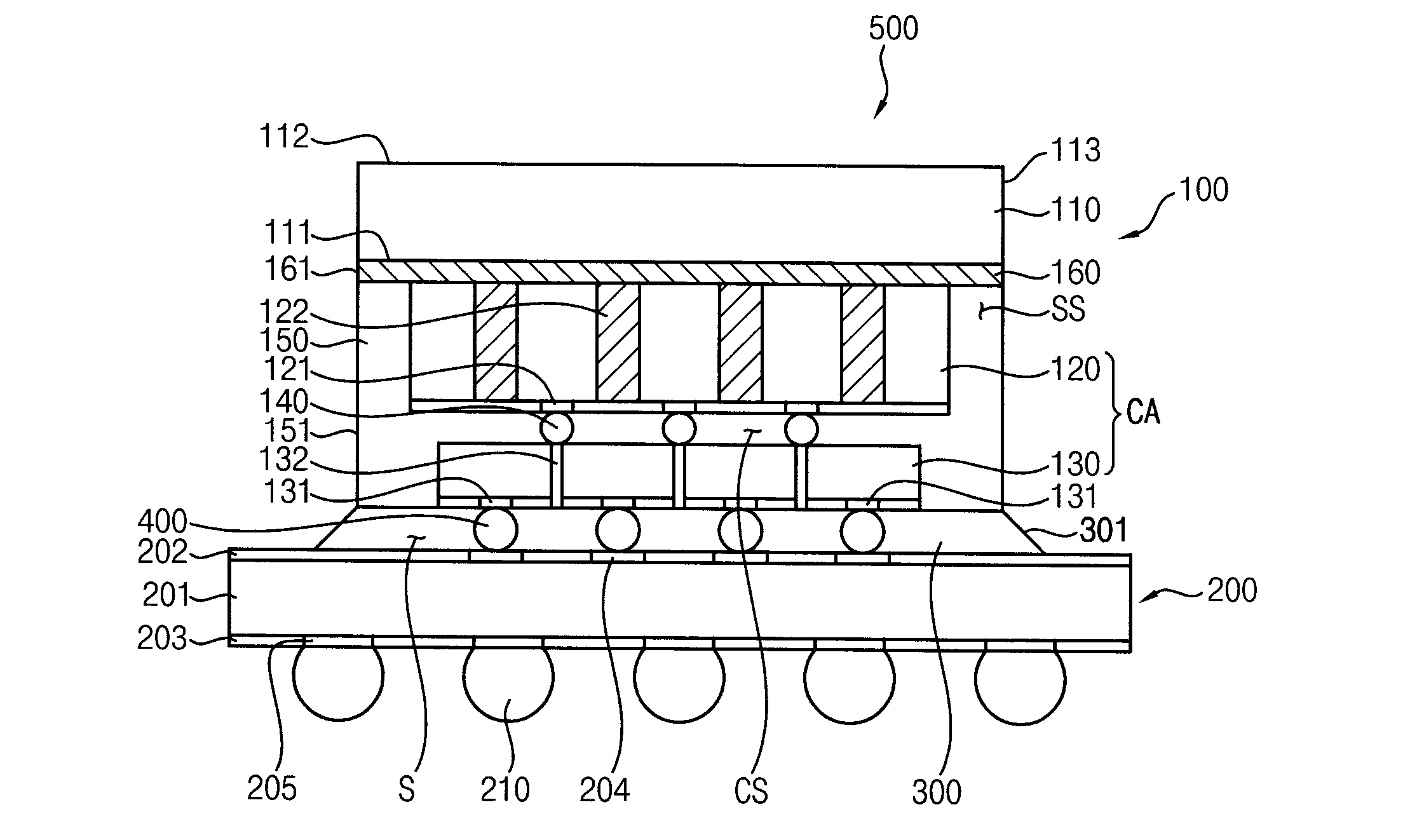
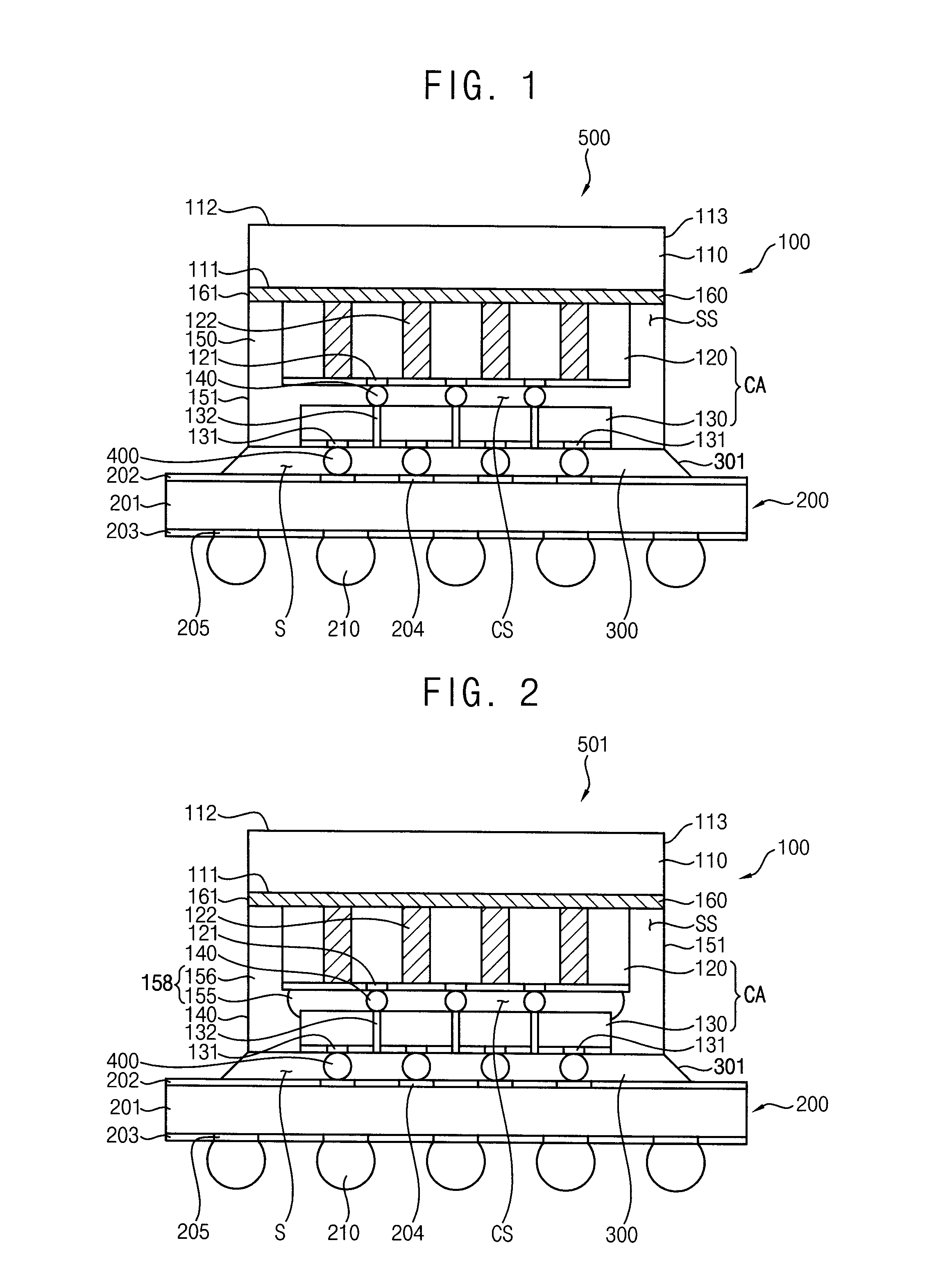
[0026]According to some example embodiments of the present inventive concepts, a plurality of integrated circuit chips may be firstly stacked on a dissipating plate and then a chip stack structure of the integrated circuit chip and the dissipating plate may be secondly mounted onto the circuit board so that a plurality of integrated circuit chips may be mounted the circuit board in a bulk. Thus, the warpage of the circuit board and the bonding failures caused by the warpage may be substantially mitigated or prevented and operational reliability of the multichip package may be increased.
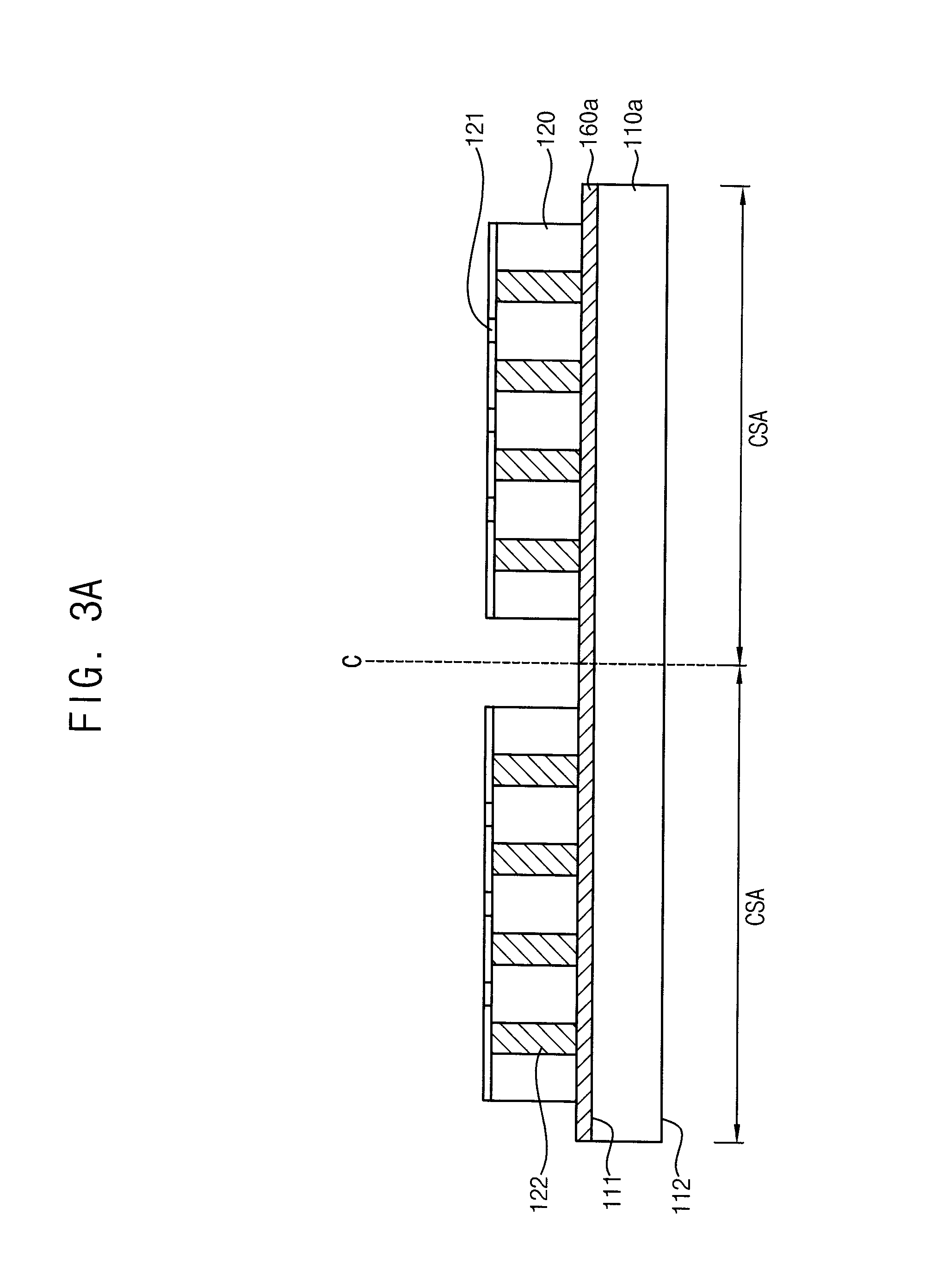
[0027]According to some example embodiments of the present inventive concepts, a plurality of first integrated circuit chips may be firstly combined to a dissipating plate and a plurality of second integrated circuit chips may be mounted on the first integrated circuit chips, thereby forming a plurality of chip assemblies. Then, the chip assemblies are separated into an individual chip stack structures. Each of the individual chip stack structures may be secondly mounted to the circuit board. Thus, the warpage of the circuit board may be substantially reduced as compared to when the first integrated circuit chip having a relatively small size may be firstly mounted on the circuit board and then the second integrated circuit chip having a relatively large size may be bonded to the first integrated circuit chip. Therefore, the bonding failures of the integrated circuit chips to the circuit board caused by the warpage may be substantially reduced, which may increase reliability of the multichip package 500.
[0028]Further, because the chip stack structure 100 including the mold layer may be mounted onto the circuit board, the surface area of the under-fill layer may be increased. Thus, the thermal resistance of the circuit board may be increased in the under-fill process and thus the warpage of the circuit board may be mitigated or prevented in the under-fill process. Further, the mechanical bonding force between the circuit board and the chip stack structure may be increased due to the increase of the surface area of the under-fill layer, which may increase reliability of the semiconductor package.

Problems solved by technology

In the conventional multichip packages, the circuit board may experience a warpage while bonding the second chip to the first chip.
Accordingly, solder bumps interposed between the circuit board and the first chip may be partially broken, and thus the first chip may not be substantially bonded to the circuit board.

Method used


Image

  • Semiconductor package and method of manufacturing the same
  • Semiconductor package and method of manufacturing the same
  • Semiconductor package and method of manufacturing the same

Examples


Embodiment Construction

[0042]Various example embodiments will be described more fully hereinafter with reference to the accompanying drawings, in which some example embodiments are shown. The present invention may, however, be embodied in many different forms and should not be construed as limited to the example embodiments set forth herein. Rather, these example embodiments are provided so that this disclosure will be thorough and complete, and will fully convey the scope of the present invention to those skilled in the art. In the drawings, the sizes and relative sizes of layers and regions may be exaggerated for clarity.

[0043]It will be understood that when an element or layer is referred to as being “on,”“connected to” or “coupled to” another element or layer, it can be directly on, connected or coupled to the other element or layer or intervening elements or layers may be present. In contrast, when an element is referred to as being “directly on,”“directly connected to” or “directly coupled to” anoth...


PUM


Abstract

A semiconductor package including a chip stack structure having first and second chips that are secured to a dissipating plate by using a mold layer such that the second chip is combined to the dissipating plate and the first chip is bonded to the second chip, and the first chip has a smaller thickness than the second chip, a circuit board onto which the chip stack structure is mounted in a bonded manner, and an under-fill layer filling a gap space between the circuit board and first chip, a side surface of the under-fill layer being connected to a sidewall of the mold layer may be provided. Due to this bulk mounting structure, the warpage and bonding failures of the semiconductor package may be substantially reduced.

Description

CROSS-REFERENCE TO RELATED APPLICATIONS[0001]This application claims priority under 35 U.S.C §119 to Korean Patent Application No. 10-2014-0015047 filed on Feb. 10, 2014 in the Korean Intellectual Property Office, the disclosure of which is incorporated by reference herein in its entirety.BACKGROUND[0002]1. Field[0003]Some example embodiments relate to semiconductor packages and methods of manufacturing the same, and more particularly, to chip stack packages and methods of manufacturing the same.[0004]2. Description of the Related Art[0005]Recently, there has been a great demand for semiconductor packages having small size and large capacity. Because the capacity of a memory chip is difficult to increase, there have been efforts to increase the capacity of the semiconductor package, for example, by vertically stacking a plurality of the conventional memory chips (multichip-type package) or by vertically stacking conventional semiconductor packages (stack-type package). In recent sma...

Claims


Application Information

Patent Timeline
Patent Type & Authority Applications(United States)
IPC IPC(8): H01L23/00H01L23/16H01L23/367H01L23/522
CPCH01L23/562H01L23/522H01L23/16H01L2224/818H01L24/17H01L24/81H01L23/367H01L2924/181H01L23/36H01L23/3677H01L23/4334H01L23/49816H01L2924/12042H01L23/3128H01L21/563H01L25/0657H01L2224/16147H01L24/97H01L2224/12105H01L2224/131H01L2224/16237H01L2224/17181H01L2224/73204H01L2224/81801H01L2224/81986H01L2224/9202H01L2224/97H01L21/561H01L24/19H01L24/20H01L2224/73259H01L2225/06589H01L2924/15311H01L2224/92224H01L2225/06513H01L2225/06541H01L2225/06524H01L2924/00H01L2924/014H01L2224/11H01L2924/00014H01L2224/81
Inventor KIM, JI-HWANGMA, KEUM-HEECHO, TAE-JE
Owner SAMSUNG ELECTRONICS CO LTD
Why Eureka
Try Eureka