Controller-integrated rotary electric machine

a technology of integrated control and rotary electric machine, which is applied in the direction of dynamo-electric machines, electrical equipment, supports/enclosements/casings, etc., can solve the problems of no longer providing correct power to the power module, deteriorating the surrounding area of the press fit of the bus bar, etc., and achieves the effect of improving the corrosion resistance of the electrolytic process

Active Publication Date: 2015-08-13
MITSUBISHI ELECTRIC CORP
View PDF3 Cites 17 Cited by
  • Summary
  • Abstract
  • Description
  • Claims
  • Application Information

AI Technical Summary

Benefits of technology

[0012]According to the controller-integrated rotary electric machine of the invention, electrolytic corrosion resistance can be improved in the electrical coupling surface between the power input / output terminal bolt and the bus bar, and the power input / output terminal bolt and the bus bar can be downsized.

Problems solved by technology

However, the conventional controller-integrated rotary electric machine as described in the Patent Document 1 has a problem that since a power input / output terminal bolt is directly pressed into the bus bar, when salt water or the like penetrates from the outside to the head of the power input / output terminal bolt, the surrounding area of the press fit of the bus bar deteriorates through electrolytic corrosion, and finally, a crack occurs in the surrounding area of the press fit of the bus bar due to engine vibration and then the correct power is no longer supplied to the power module.
Furthermore, another problem is that the bus bar needs a press fit length that provides a mechanical joint surface and also, in view of the above-described problem, needs an unnecessarily large thickness of the bus bar irrespective of heat generation by electricity, leading to upsizing.

Method used


Image

  • Controller-integrated rotary electric machine
  • Controller-integrated rotary electric machine
  • Controller-integrated rotary electric machine

Examples


first embodiment

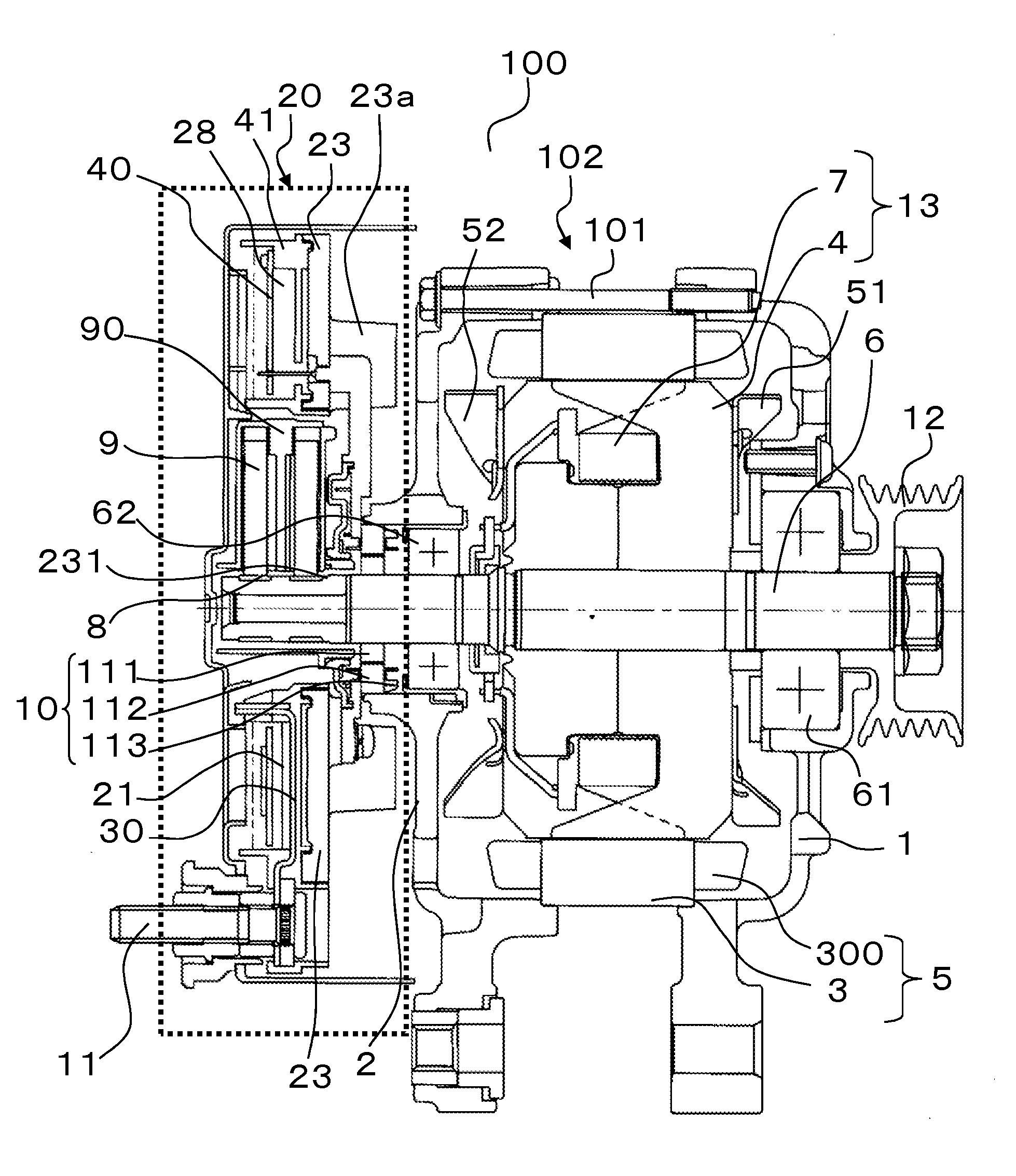
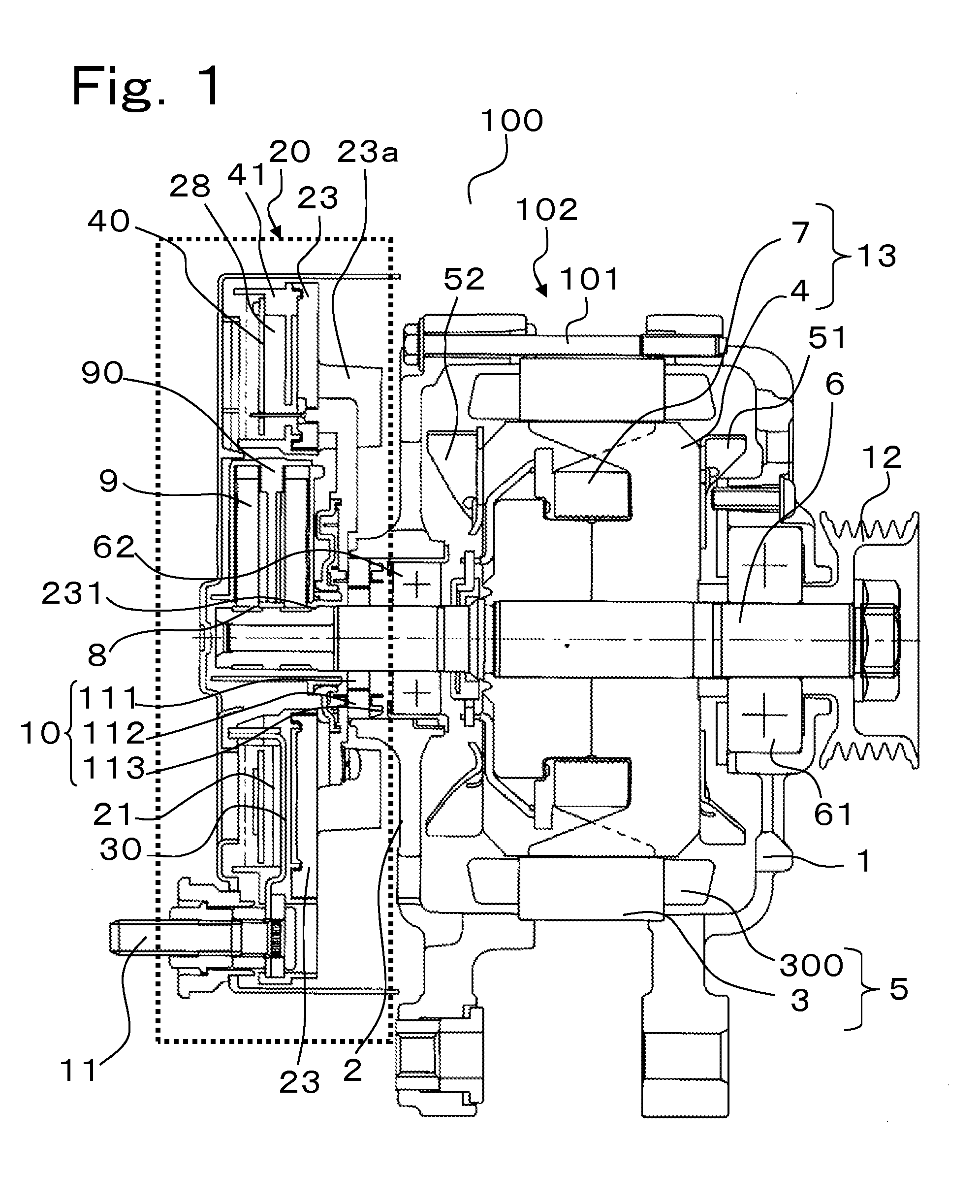
[0018]FIG. 1 is a vertical cross-sectional view of a controller-integrated rotary electric machine in accordance with a first embodiment of the invention.

[0019]In FIG. 1, a controller-integrated rotary electric machine for vehicle 100 includes: a stator core 3 supported by a front bracket 1 and a rear bracket 2; and a rotor core 4 inserted into the inside space of the stator core 3. The rotor core 4 includes a plurality of rotor poles facing the inner circumference surface of the stator core 3 with an air gap in between.

[0020]A stator winding 300 that is an armature winding in which a coil piece is inserted into a slot of the stator core 3 is fixed to the stator core 3. In the first embodiment, the stator winding 300 is six-phase connected. A rotor winding 7 that is a field winding is fixed to the rotor core 4. The stator core 3 and the stator winding 300 form a stator 5 of a rotary electric machine main body 102. The rotor core 4 and the rotor winding 7 form a rotor 13 of the rotar...


PUM


Abstract

A controller-integrated rotary electric machine with electrolytic corrosion resistance improved can be obtained. The controller-integrated rotary electric machine includes: a power circuit unit provided between an external power supply and a stator winding of a rotary electric machine main body; a power input/output terminal bolt provided in the power circuit unit and electrically connected to the external power supply; a plate pressed into the power input/output terminal bolt and abutting a power input/output conductor; a bus bar connected to the power input/output conductor; and a power module connected to the bus bar and the stator winding, wherein the power input/output terminal bolt and the bus bar are separated from each other.

Description

BACKGROUND OF THE INVENTION[0001]1. Field of the Invention[0002]The present invention relates to a controller-integrated rotary electric machine in which a rotary electric machine and a controller for controlling the rotary electric machine are integrally configured.[0003]2. Description of the Related Art[0004]A controller-integrated rotary electric machine mounted on a vehicle, such as a car, includes a power conversion circuit for power conversion between an armature winding of the rotary electric machine and a battery provided outside the rotary electric machine. The power conversion circuit generally includes a plurality of power modules containing a semiconductor based switching device and operates as an inverter or converter under control by a gate signal applied to the gate of these switching devices.[0005]When the rotary electric machine is caused to operate as a motor, the power conversion circuit is caused to operate as an inverter that converts DC power of the battery int...

Claims


Application Information

Patent Timeline
Patent Type & Authority Applications(United States)
IPC IPC(8): H02K3/28H02K11/00
CPCH02K3/28H02K11/0073H02K11/0094H02K5/225H02K11/05
Inventor KASHIHARA, TOSHIAKIUTSUMI, YOSHINOBU
Owner MITSUBISHI ELECTRIC CORP
Why Eureka
Try Eureka