Point-to-Point Fiber Insertion

a technology of telecommunications signal and fiber insertion, which is applied in the direction of waterborne vessels, electric cable installations, earthwork drilling and mining, etc., can solve the problems of low labor costs and/or equipment costs, and achieve the effects of low cost, low labor costs and/or equipment costs, and minimal ecological impa

Active Publication Date: 2015-08-13
CENTURYLINK INTPROP
View PDF7 Cites 38 Cited by
  • Summary
  • Abstract
  • Description
  • Claims
  • Application Information

AI Technical Summary

Benefits of technology

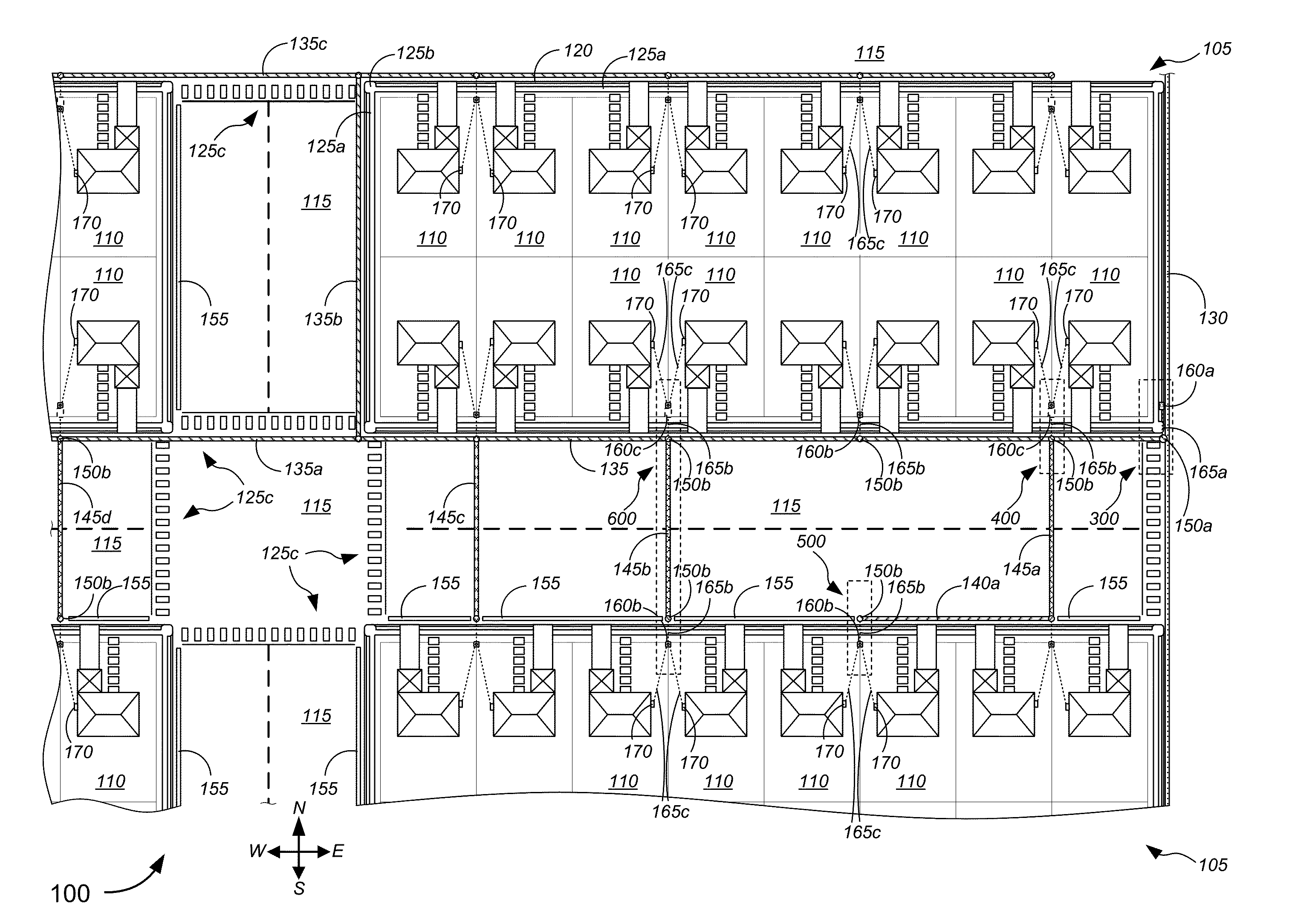
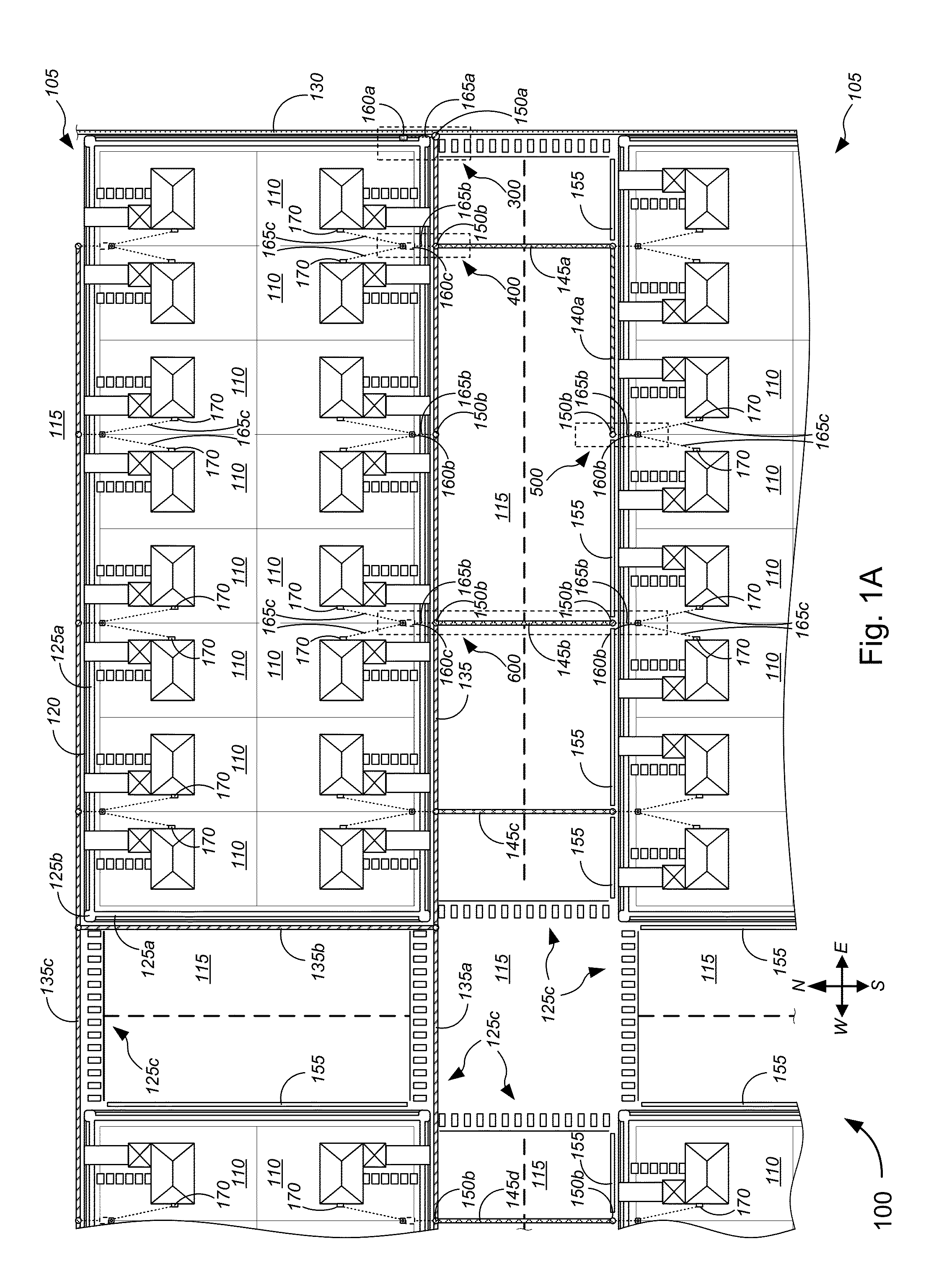
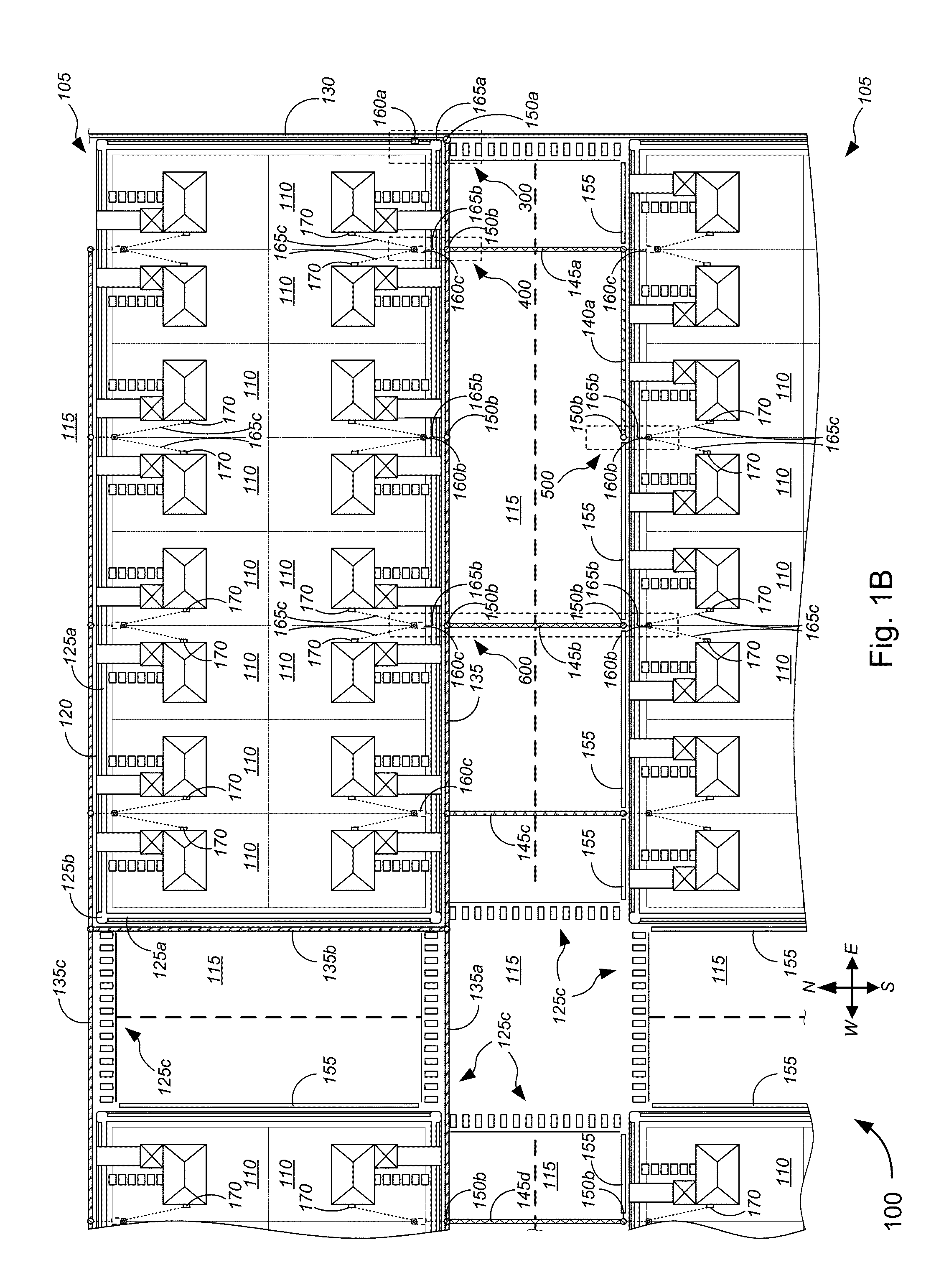
[0011]Some advantages of the systems described herein include, without limitation, relatively low costs, efficiency, flexibility, system strength and reliability, minimal ecological impact, visual unobstructiveness, and/or the like, especially in conjunction with the use of surface trenching techniques as applied to apical conduit systems and the use of ground-based signal distribution systems. Herein, surface trenching refers to a technique that is not unlike conventional micro-trenching techniques, except that trenching is within the top layer (e.g., asphalt layer or concrete layer, etc.) and not below the top layer. Because surface trenching for apical conduit systems require smaller profile channels or trenches compared to other buried solutions, labor costs and/or equipment costs may be kept low. Surface trenching also allows for flexibility in terms of routing and laying channels and surface trenches, relatively high system strength due to the use of polyurea and/or other thermosetting materials that have been proven in lab tests to have similar (and sometimes better) strength characteristics compared to asphalt (in which the channels or surface trenches are laid) thus leading to reliability, minimal ecological impact due to similar impact compared to asphalt and the like, efficiency in terms of implementing FTTP using apical conduit system techniques and in terms of line repair (as descri

Problems solved by technology

Because surface trenching for apical conduit systems require smaller profile channels or tre

Method used


Image

  • Point-to-Point Fiber Insertion
  • Point-to-Point Fiber Insertion
  • Point-to-Point Fiber Insertion

Examples


Embodiment Construction

[0043]While various aspects and features of certain embodiments have been summarized above, the following detailed description illustrates a few exemplary embodiments in further detail to enable one of skill in the art to practice such embodiments. The described examples are provided for illustrative purposes and are not intended to limit the scope of the invention.

[0044]In the following description, for the purposes of explanation, numerous specific details are set forth in order to provide a thorough understanding of the described embodiments. It will be apparent to one skilled in the art, however, that other embodiments of the present invention may be practiced without some of these specific details. In other instances, certain structures and devices are shown in block diagram form. Several embodiments are described herein, and while various features are ascribed to different embodiments, it should be appreciated that the features described with respect to one embodiment may be i...


PUM

PropertyMeasurementUnit
Timeaaaaaaaaaa
Electrical conductoraaaaaaaaaa
Thermosettingaaaaaaaaaa

Abstract

Novel tools and techniques are provided for implementing point-to-point fiber insertion within a passive optical network (“PON”) communications system. The PON communications system, associated with a first service provider or a first service, might include an F1 line(s) routed from a central office or DSLAM to a fiber distribution hub (“FDH”) located within a block or neighborhood of customer premises, via at least an apical conduit source slot, an F2 line(s) routed via various apical conduit components to a network access point (“NAP”) servicing customer premises, and an F3 line(s) distributed, at the NAP and from the F2 line(s), to a network interface device or optical network terminal at each customer premises via various apical conduit components (e.g., in roadway surfaces). Point-to-point fiber insertion of another F1 line(s), associated with a second service provider or a second service, at either the NAP or the FDH (or outside these devices).

Description

CROSS-REFERENCES TO RELATED APPLICATIONS[0001]This application claims priority to U.S. patent application Ser. No. 61 / 939,109 (the “'109 Application”), filed Feb. 12, 2014 by Michael L. Elford et al. (attorney docket no. 020370-015901US), entitled, “Point-to-Point Fiber Insertion.”[0002]This application may also be related to U.S. patent application Ser. No. 61 / 893,034 (the “'034 Application”), filed Oct. 18, 2013 by Michael L. Elford et al. (attorney docket no. 020370-013901US), entitled, “Fiber-to-the-Home (FTTH) Methods and Systems”; U.S. patent application Ser. No. 14 / 517,574 (the “'574 Application”), filed on Oct. 17, 2014 by Michael L. Elford et al. (attorney docket no. 020370-013900US), entitled, “Fiber-to-the-Premises (FTTP) Methods and Systems,” which claims priority to the '034 Application”; U.S. patent application Ser. No. 61 / 874,691 (the “'691 Application”), filed Sep. 6, 2013 by Thomas Schwengler et al. (attorney docket no. 020370-012501US), entitled, “Wireless Distribu...

Claims


Application Information

Patent Timeline
IPC IPC(8): H04Q11/00G02B6/44G02B6/50
CPCH04Q11/0067G02B6/504G02B6/4452H04Q11/0003G02B6/4416G02B6/4483G02B6/4451G02B6/4459G02B6/4442Y10T29/4998G02B6/501
Inventor ELFORD, MICHAEL L.WINTERROWD, MICHAEL P.BARNETT, JR., THOMAS C.SCHWENGLER, THOMAS
Owner CENTURYLINK INTPROP
Why Eureka
Try Eureka