Enhanced oil recovery process to inject surfactant-augmented low-salinity water in oil-wet carbonate reservoirs

a technology of surfactant and hydrocarbon reservoir, which is applied in the direction of fluid removal, chemistry apparatus and processes, and wellbore/well accessories, etc., can solve the problems of low success rate of chemical eor in general and a nonionic surfactant field application, high cost of full field low salinity water injection, and reduced salinity of reservoirs. , to achieve the effect of enhancing oil recovery, improving economics, and improving the ultimate recovery of the field

Inactive Publication Date: 2015-08-20
COLORADO SCHOOL OF MINES
View PDF2 Cites 24 Cited by
  • Summary
  • Abstract
  • Description
  • Claims
  • Application Information

AI Technical Summary

Benefits of technology

[0015]iii. This process may be implemented as an alternating low-salinity-surfactant system to improve economics.
[0016]The concentration of surfactant diluted in low-salinity water may be between about 500 ppm to 10,000 ppm. Hence, the surfactant will be effective in mobilizing residual oil.
[0017]By way of example, this EOR process can be applied to one of the largest carbonate reservoir, Upper Zakum, located offshore Abu Dhabi. This reservoir is currently undergoing conventional seawater flooding at injection rate of 800 MBW/day. The average daily oil production is about 560 MSTB. The surfactant with low-salinity water EOR process described herein can have a potential impact to improve ultimate recovery of the field.
[0018]An aspect of the invention is a method to enhance recovery of oil in a hydrocarbon reservoir. The method includes injecting low-salinity water into the reservoir. The low-salinity water injection is followed by an injection of a surfactant diluted in an additional low salinity water. The salinity of the additional low-salinity water is less than the salinity of the low-salinity water.
[0019]Another aspect of the invention is a method to enhance oil recovery from a hydrocarbon reservoir. The method includes injecting a high salinity water into the reservoir. The injection of the high

Problems solved by technology

During seawater flooding, the salinity of reservoirs decreases but not low enough to be favorable for surfactant flooding.
Due to this fact, the success of chemical EOR in general and a

Method used


Image

  • Enhanced oil recovery process to inject surfactant-augmented low-salinity water in oil-wet carbonate reservoirs
  • Enhanced oil recovery process to inject surfactant-augmented low-salinity water in oil-wet carbonate reservoirs
  • Enhanced oil recovery process to inject surfactant-augmented low-salinity water in oil-wet carbonate reservoirs

Examples


examples

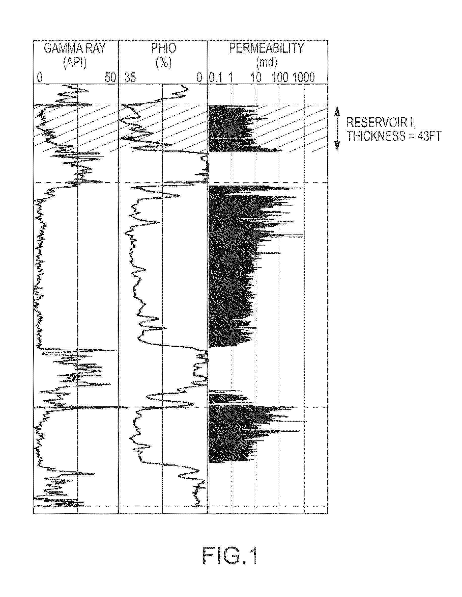
[0105]The potential of low-salinity waterflooding and surfactant diluted in low-salinity water was investigated using cores from reservoir I cores. Three sets of low-salinity waterfloods were performed following the seawater flood, each with five pore volumes (PV). The fluid for the first low-salinity flood (LS1) was created by diluting the seawater by a factor of two (25,679 ppm). Similarly LS2 contains diluted seawater by a factor of 4 (12,840 ppm) and LS3 contains diluted seawater by a factor of 50 (1,027 ppm). The incremental oil recovery of the first two EOR low-salinity waterfloods are 6.2% and 1.1% respectively. No additional oil was recovered during the third low-salinity waterflood. An additional 5% oil recovery was obtained after the subsequent flood of surfactant diluted in low-salinity water (LS2). A constant 0.1 cm3 / min injection rate was applied to each of the three low-salinity waterfloods and surfactant diluted in low-salinity water

Setup

[0106]Coreflood experiments we...

experiment 1

[0126]FIG. 6 illustrates a schematic diagram of the low salinity waterflood followed by surfactant diluted in low-salinity waterflooding process and core flooding experiment set up. The production fluid is collected in graduated cylinders using a fraction collector. The graduated tubes are then centrifuged in measure oil production and fluid analysis. For the first experiment, three sets of low-salinity waterfloods were performed following the seawater flood, each with five PV. The fluid for the first low-salinity flood (LS1) was created by diluting the seawater by a factor of two (about 25,679 ppm). Similarly LS2 contains diluted seawater by a factor of 4 (about 12,840 ppm) and LS3 contains diluted seawater by a factor of 50 (about 1,027 ppm). Table 2 illustrates the composition of the seawater (SW) and three sets of low-salinity water (LS1, LS2, and LS3). The incremental oil recovery of the first two EOR low-salinity waterfloods was about 6.2% and about 1.1% respectively. No addit...

experiment 2

[0128]For the second experiment, the same protocol was performed as the first experiment. The incremental oil recovery of the first two EOR low-salinity waterfloods are 4.8% and 0.8% respectively. No additional oil was recovered during the third low-salinity waterflood. A constant injection rate of about 0.1 cm3 / min was applied to each of the three low-salinity waterfloods. A final flood with five PV of non-ionic surfactant (about 1,000 ppm) mixed with the LS2 fluid was performed at a flow rate of about 0.1 cm3 / mm. After this flood, an incremental oil recovery of about 4.9% was obtained. FIG. 8 illustrates the oil recovery factor and pressure drop across the core (ΔP) as a function pore volume injected during the different floods (seawater flood (WF), the three sets of low-salinity waterflood [LS1, LS2, and LS3], and the non-ionic surfactant flood diluted in LS2 fluid). FIG. 8 illustrates the RF and pressure difference between injection and production end (ΔP) as a function pore vol...


PUM


Abstract

The present invention relates to a method to enhance oil recovery from a hydrocarbon reservoir. One aspect of the invention includes injecting low salinity water into the reservoir followed by the injection of a surfactant diluted in low salinity water, and alternating the injections of the low salinity water and the surfactant diluted in the low salinity water. The invention improves the effectiveness of the surfactant by reducing the salinity of the reservoir by injecting low-salinity water into the reservoir.

Description

CROSS REFERENCE TO RELATED APPLICATIONS[0001]This application claims priority under 35 U.S.C. §119(e) to U.S. Provisional Patent Application Ser. No. 61 / 946,062 filed Feb. 28, 2014, which is incorporated herein in its entirety by reference. This application is a Continuation-in-Part of U.S. patent application Ser. No. 14 / 626,362, filed on Feb. 19, 2015, which claims priority under 35 U.S.C. §119(e) to U.S. Provisional Patent Application Ser. No. 61 / 941,869 filed Feb. 19, 2014. Each of these applications is incorporated by reference in their entirety.FIELD OF THE INVENTION[0002]The invention relates to a method to enhance the recovery of oil in a hydrocarbon reservoir with the injection of low salinity water and a surfactant.BACKGROUND[0003]Conventional water flooding is widely used globally in carbonate oil reservoirs. The ultimate oil recovery from primary production and high salinity waterflooding is significantly less than 50%. To recover additional residual oil after a high sali...

Claims


Application Information

Patent Timeline
IPC IPC(8): E21B43/20C09K8/584
CPCE21B43/20C09K8/584
Inventor ALAMERI, WALEED SALEMTEKLU, TADESSE WELDUGRAVES, RAMONA M.KAZEMI, HOSSEINALSUMAITI, ALI M.
Owner COLORADO SCHOOL OF MINES
Why Eureka
Try Eureka