Optical fill detection

a technology of optical filling and detection field, which is applied in the field of home monitoring, can solve the problems of low blood cell count patients in danger of serious complications, inability to receive their next treatment, and failure due to incorrect filling, and achieve the effect of high likelihood

Inactive Publication Date: 2015-08-20
KONINKLIJKE PHILIPS ELECTRONICS NV
View PDF2 Cites 9 Cited by
  • Summary
  • Abstract
  • Description
  • Claims
  • Application Information

AI Technical Summary

Benefits of technology

[0005]The present invention addresses these needs and provides devices comprising an automatic fill detection feature. The above objective is in particular accomplished by a device for the analysis of sample material a device for the analysis of sample material comprised in a sample volume, comprising a light source, wherein said light source is configured for irradiating the sample volume; a detector, wherein said detector is configured to detect light from said sample volume in response to an irradiation of said sample volume by the light source; and an assessment unit for assessing the fill level of said sample volume based on the detected light. It was in particular found by the inventors that a device as described allows to prevent a test being performed when it is already known that the test will fail with high likelihood. A detection of filling problems, e.g. due to the presence of voids or air bubbles, can advantageously be displayed to the user to inform her or him that sample volume has not been filled correctly and that intervention is required, e.g. by a repetition of the filling activity.
[0009]In a further preferred embodiment said light source is configured to emit light having a wavelength of 475-575 nm or 260-350 nm. The use of green light in the range of 475-575 nm provides the advantageous effect that substances which absorb light of this wavelength range can be detected. Red blood cells, in particular hemoglobin absorbs light of the indicated range quite well. Similarly, further bodily fluids such as urine can be detected, e.g. by the use of different wavelength in the range of 260-350 nm. Urine accordingly absorbs light having this wavelength. The presence of blood via the absorption of light by hemoglobin or the presence of urine via the absorption of urea or uric acid can accordingly be detected. The detection of such absorbances accordingly allows for the determination whether a correct filling is given in the sample volume or not.
[0012]In yet another preferred embodiment of the present invention the device as mentioned herein above comprises scanning means configured to detect light from the entire sample volume. The detection of light from the entire sample volume provides the advantageous effect that potential blind spots at positions of air bubbles or other filling discrepancies are largely avoided. It is preferred that the scanning means to be used is a camera.
[0014]In a further aspect the present invention relates to a sample container configured for holding sample material in a sample volume comprising a valve configured for moving said sample material. Within the sample container sample material such as blood or other bodily fluids may accordingly be transported from an opening section to a testing or control section, or from a top position to a bottom position. The valve may have suitable forms in order to allow for an optical detection of the fluid transport process in the sample volume. It is preferred that said valve is configured for changing the direction of at least part of impinging light upon irradiation of the sample volume. In a further preferred embodiment of the invention the valve comprises a rounded edging or a radial edging. Blind spots may be present at sites of non-optimal fillings, e.g. due to the presence of voids or gaps in the bodily fluid to be tested and lead to a potential failure to detect non-correct filling states of the sample volume within the sample container. Since blind spots typically occur in the valve section of the sample container, a rounded or radial edging of the valve advantageously reduces the maximum area of blind spots due to increased optical detection.
[0016]In yet another preferred embodiment of the invention the valve as mentioned herein above is transparent. A transparent valve may comprise or is made of transparent plastic material. In a particularly preferred embodiment said valve comprises or is made of polycarbonate material. The transparency of valve material was found to further increase the optical properties of the valve and thus the image quality. It was accordingly found that the use of transparent material, such as polycarbonate material, advantageously improves image quality and reduces the maximum area of blind spots due to increased optical detection.
[0022]This method advantageously allows detecting the presence of bodily fluids or substances which absorb light of the wavelength range of 475-575 nm or 260-350 nm. Among bodily fluids which are detectable by irradiation with a wavelength of 475-575 nm is blood comprising hemoglobin which absorbs light of the indicated range quite well. Similarly, further bodily fluids such as urine can be detected, e.g. by the use of different wavelengths in the range of 260-350 nm. The detection of such absorbance in the indicated wavelength ranges accordingly allows for the assessment of the fill level of the sample volume.

Problems solved by technology

Patients with low blood cell counts are in danger of serious complications from an infection, as well as not being able to receive their next treatment due to low cell counts.
A typical problem, which frequently occurs during the handling of such devices, is their failing due to incorrect filling, e.g. with a bodily fluid such as blood or urine.
An accurate analysis of bodily fluid parameters requires a correct filling of the analysis device since wrong volumes or the presence of air bubbles would lead to unusable or incorrect results.
Furthermore, incorrect fillings of a device which are not detected before starting the analysis of the bodily fluid may lead to an increased failure rate of the testings and an increased number of test repetitions thus raising the associated operation costs.

Method used


Image

  • Optical fill detection
  • Optical fill detection
  • Optical fill detection

Examples


example 1

Detection of Blind Spots by Different Imaging Techniques

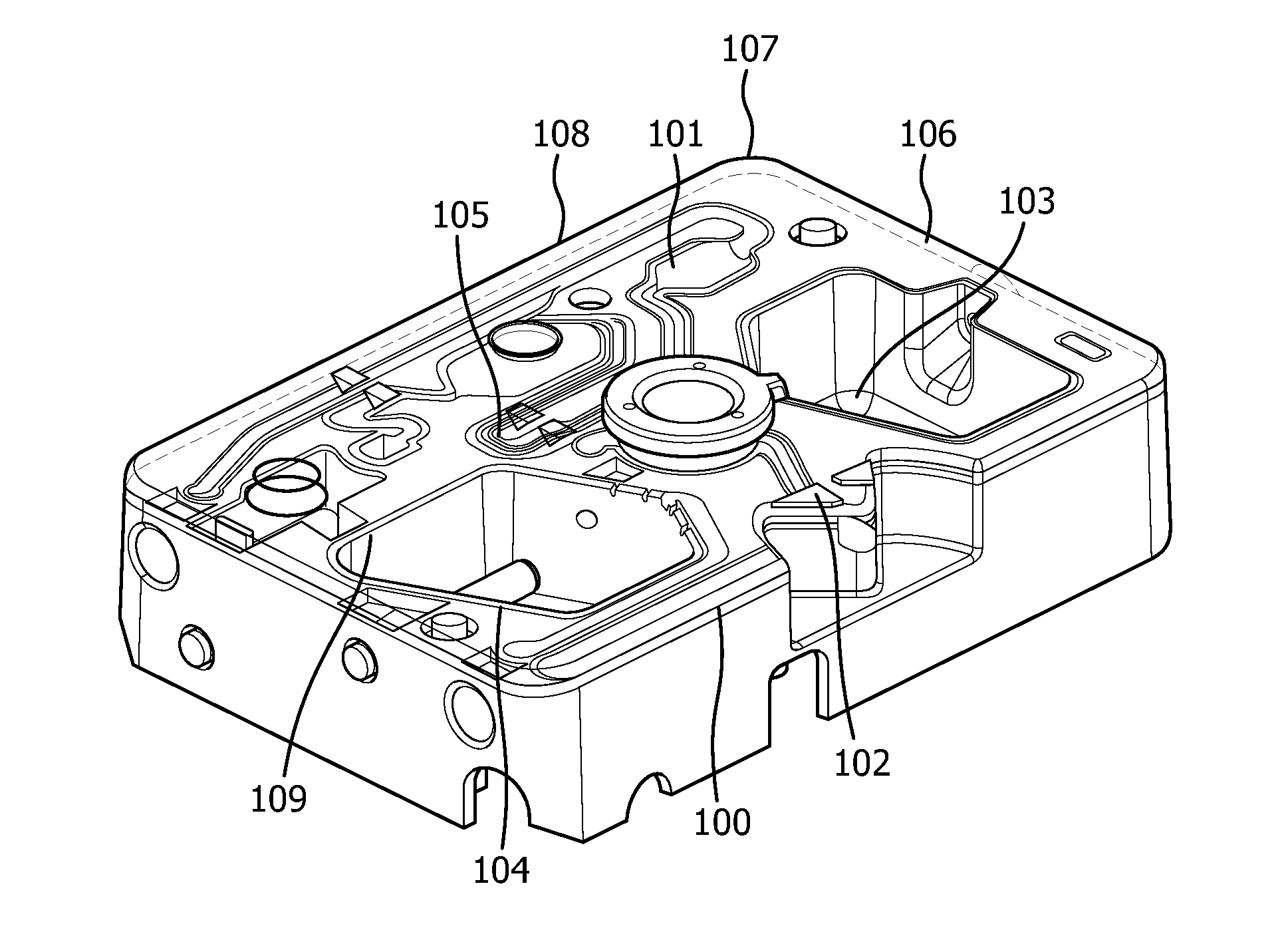
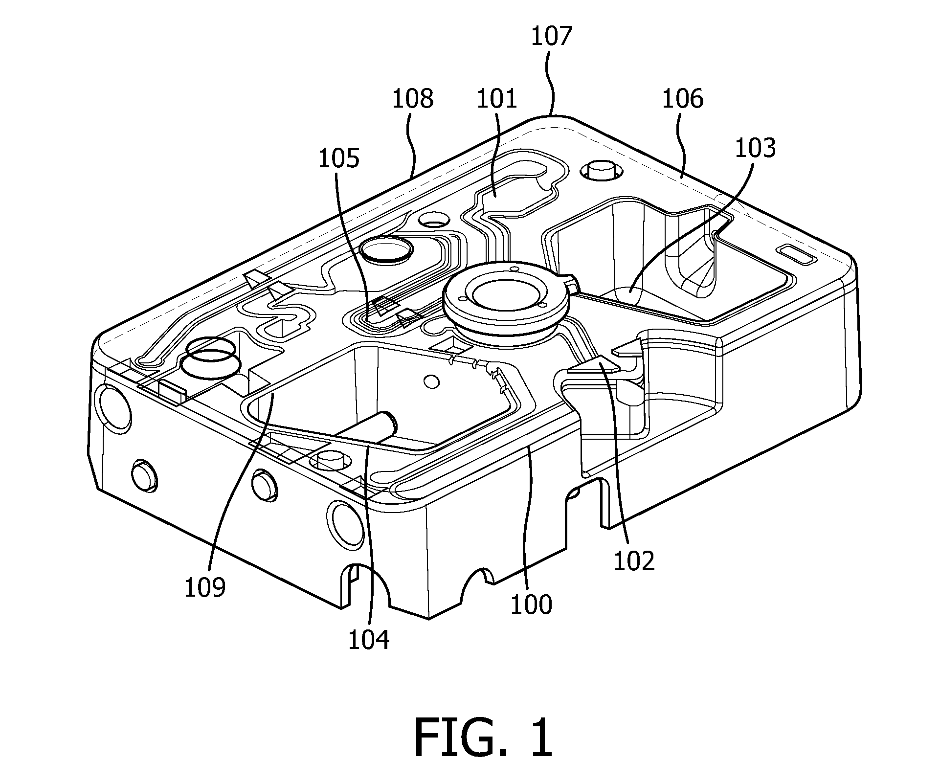
[0164]The device described in the invention advantageously allows automatic fill detection to take place. This solution works in particular well if the air bubble or defect is in the middle of a valve. There may be, however, a part of a valve that cannot be imaged using a standard light source and detector. In order to improve the system setup, different image and lens options were tested. The tested options are indicated in Table 1, below.

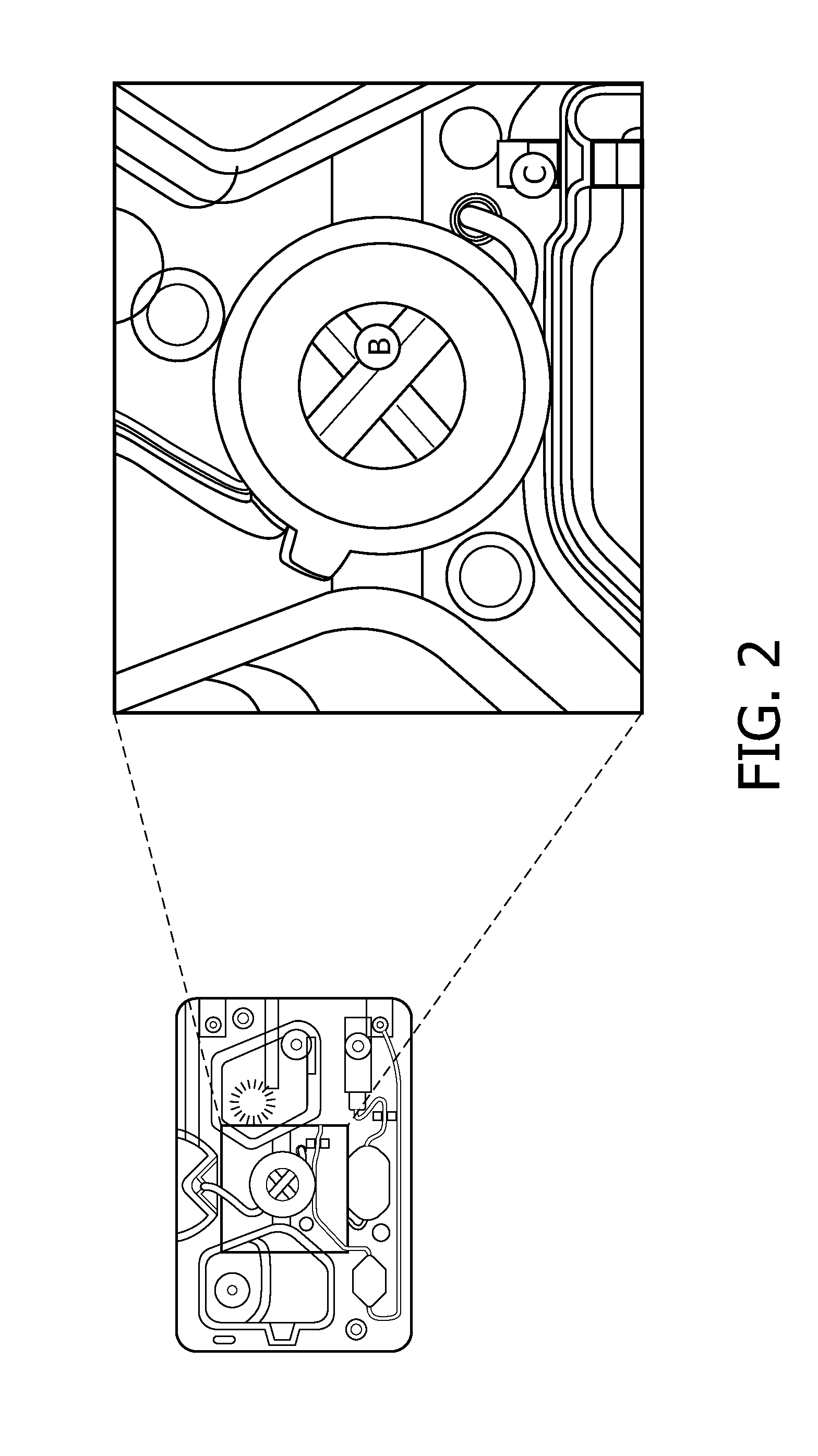
[0165]Option A is standard imaging. The blind distance from the wall was found to be 12.6 to 12% on each side, i.e. greater than a 10% deviation.

[0166]Option B involves using a lens in the cartridge. The blind distance from the wall was found to be 10.5-9.8% on each side.

[0167]Option C requires the camera to be mechanically maneuvered into the valve to extend the field of vision. The blind distance from the wall was found to be 9.8 to 9.1% on each side.

TABLE 1OptionA - Normal ImagingB - Field...


PUM


Abstract

The present invention relates to the field of home monitoring. In particular the present invention relates to a device for the analysis of sample material, comprising a sample container, wherein said sample container is configured for holding sample material, a light source, wherein said light source is configured for irradiating the sample container a detector, wherein said detector is configured to detect light from the sample container in response to an irradiation of the sample container by the light source and an assessment unit for assessing the fill level of the sample container based on the detected light, as well as the use of such a device for home monitoring parameters of a bodily fluid of a subject. The present invention further relates to a method for assessing the fill level of a sample container configured for holding sample material.

Description

FIELD OF THE INVENTION[0001]The present invention relates to the field of home monitoring. In particular the present invention relates to a device for the analysis of sample material comprised in a sample volume, comprising a light source, wherein said light source is configured for irradiating the sample volume; a detector, wherein said detector is configured to detect light from said sample volume in response to an irradiation of said sample volume by the light source; and an assessment unit for assessing the fill level of said sample volume based on the detected light. The present invention further relates to a sample container configured for holding sample material in a sample volume comprising a valve configured for moving said sample material, wherein said valve is configured for changing the direction of at least part of impinging light upon irradiation of the sample volume. The present invention also relates to a method for assessing the fill level of a sample volume configu...

Claims


Application Information

Patent Timeline
Patent Type & Authority Applications(United States)
IPC IPC(8): G01F23/292A61B10/00
CPCG01N35/1016G01N2035/1018G01N2035/1025B01L3/502715B01L2300/0654B01L2300/0832B01L2300/0838B01L2300/168G01F23/2922A61B10/007G01F25/20G01F23/292
Inventor BLAKE, ROBERT LLOYDKENT, NICHOLAS YOUNG
Owner KONINKLIJKE PHILIPS ELECTRONICS NV
Why Eureka
Try Eureka