Wireless power transmission system and power transmitting device

Active Publication Date: 2015-08-20
PANASONIC CORP
View PDF3 Cites 22 Cited by
  • Summary
  • Abstract
  • Description
  • Claims
  • Application Information

AI Technical Summary

Benefits of technology

[0007]With one aspect of the present disclosure, the safe an

Problems solved by technology

As the power consumption of the mobile device operated by a battery of a predeter

Method used


Image

  • Wireless power transmission system and power transmitting device
  • Wireless power transmission system and power transmitting device
  • Wireless power transmission system and power transmitting device

Examples


first embodiment

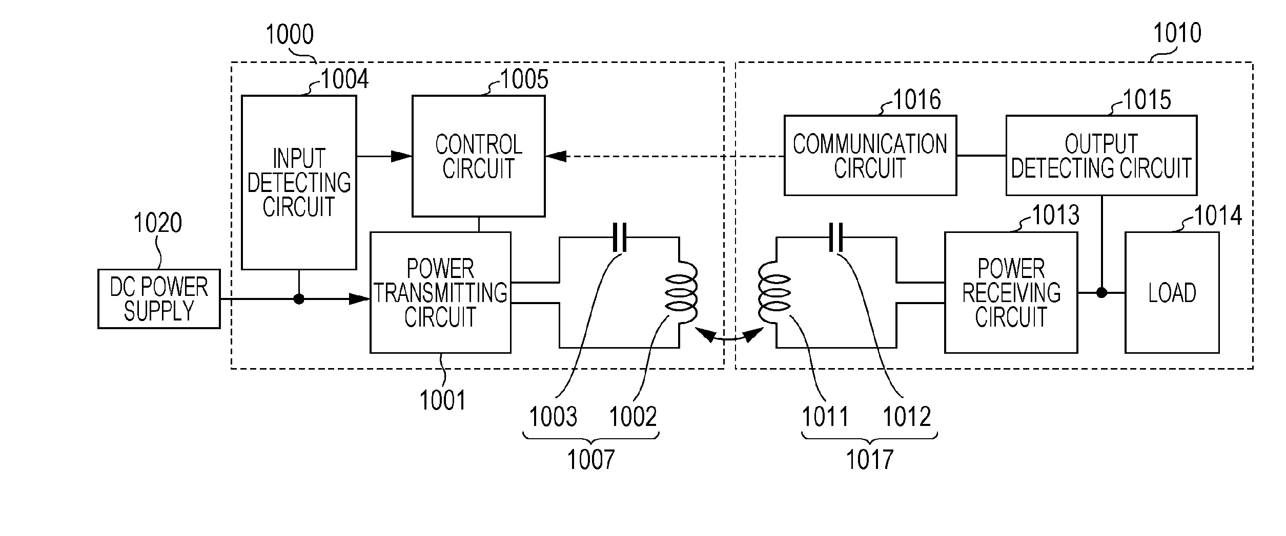
[0051]FIG. 4 is a block diagram illustrating configuration of a wireless power transmission system according to a first embodiment of the present disclosure. The wireless power transmission system includes a power transmitting device 1000 and a power receiving device 1010. In this system, electric power is transmitted from the power transmitting device 1000 to the power receiving device 1010 in a noncontact manner. The power transmitting device 1000 includes a power transmitting circuit 1001 that converts direct current (DC) power input from a DC power supply 1020 to AC power and that outputs the converted AC power, and a power transmitting antenna 1007 that transmits the AC power output from the power transmitting circuit 1001 in a noncontact manner. The power transmitting antenna 1007 includes a power transmitting coil 1002 and a resonance capacitor 1003 that is connected between the power transmitting circuit 1001 and the power transmitting coil 1002. The power receiving device 1...

second embodiment

[0095]FIG. 9 is a block diagram illustrating detailed configuration of a power transmitting device 1000 according to a second embodiment of the present disclosure. In FIG. 9, components in common or corresponding to those in FIG. 5 are denoted by the same reference numerals, and description of common matters is not repeated.

[0096]In this embodiment, the control circuit 1005 controls an output time ratio of the voltage, which is output from the power transmitting circuit 1001, such that the voltage output from the power receiving circuit 1013 is maintained at constant. The control circuit 1005 in this embodiment further includes an output time ratio control unit 1033 and an optimum output time ratio detecting unit 1034. The output time ratio control unit 1033 controls the output time ratio of the voltage, which is output from the power transmitting circuit 1001. The DC voltage output from the power receiving circuit 1013 can be changed by changing the output time ratio of the output ...

third embodiment

[0112]FIG. 15 is a block diagram illustrating detailed configuration of a power transmitting device 1000 according to a third embodiment of the present disclosure. In FIG. 15, components in common or corresponding to those in FIG. 9 are denoted by the same reference numerals, and description of common matters is not repeated.

[0113]The power transmitting device 1000 in this embodiment further includes an input voltage conversion circuit 1006 connected between the DC power supply 1020 and the power transmitting circuit 1001. The input voltage conversion circuit 1006 can change the magnitude of the DC voltage supplied to the power transmitting circuit 1001. The control circuit 1005 further includes an input voltage control unit 1035 that controls the voltage input from the input voltage conversion circuit 1006 to the power transmitting circuit 1001 (hereinafter referred to as the “input voltage”), and an optimum input voltage detecting unit 1036 that decides an optimum input voltage.

[0...


PUM


Abstract

A power transmitting device includes a power transmitting circuit that converts second DC power input from a DC power supply to AC power, a power transmitting antenna and a control circuit that receives a voltage value of the first DC power from the power receiving device. The control circuit changes a frequency of the AC power that is transmitted to the power receiving antenna, detects, from the received voltage values, a first frequency corresponding to a local minimum value of the voltage values and a second frequency corresponding to the voltage value that takes a local maximum value at a frequency higher than the first frequency, and sets the frequency of the AC power transmitted to the power receiving antenna to a frequency between the first frequency and the second frequency.

Description

BACKGROUND[0001]1. Technical Field[0002]The present disclosure relates to a wireless power transmission system and a power transmitting device, which are used to transmit electric power between a power transmitting antenna and a power receiving antenna in a noncontact manner.[0003]2. Description of the Related Art[0004]Recently, a variety of mobile devices, such as a cellular phone, have become widespread, and power consumption of each mobile device has increased more and more with improvements of function and performance and diversification of contents. As the power consumption of the mobile device operated by a battery of a predetermined capacity increases, an operation lasting time of the mobile device shortens. A wireless power transmission system receives attention as a technique to compensate for a limitation of the battery capacity. The wireless power transmission system transmits electric power from a power transmitting device to a power receiving device in a noncontact mann...

Claims


Application Information

Patent Timeline
IPC IPC(8): H02J5/00H02J17/00
CPCH02J17/00H02J5/005H02J7/025H02J50/80H02J50/12H02J7/00034H02J50/402H02J50/60
Inventor MATSUMOTO, HIROMUKANNO, HIROSHIYAMAMOTO, HIROSHISAKATA, TSUTOMU
Owner PANASONIC CORP
Why Eureka
Try Eureka