Devices and Methods for Duplexer Loss Reduction

a duplexer and loss reduction technology, applied in the field of rf (radio frequency) circuits, can solve the problems of increasing complexity of radio frequency (rf) devices such as cell phone transmitters, complex modulation schemes, modulation bandwidths, etc., and achieve the effects of reducing a number of filter stages, and reducing the loss of a transmit rf signal

Inactive Publication Date: 2015-08-20
PSEMI CORP
View PDF5 Cites 32 Cited by
  • Summary
  • Abstract
  • Description
  • Claims
  • Application Information

AI Technical Summary

Benefits of technology

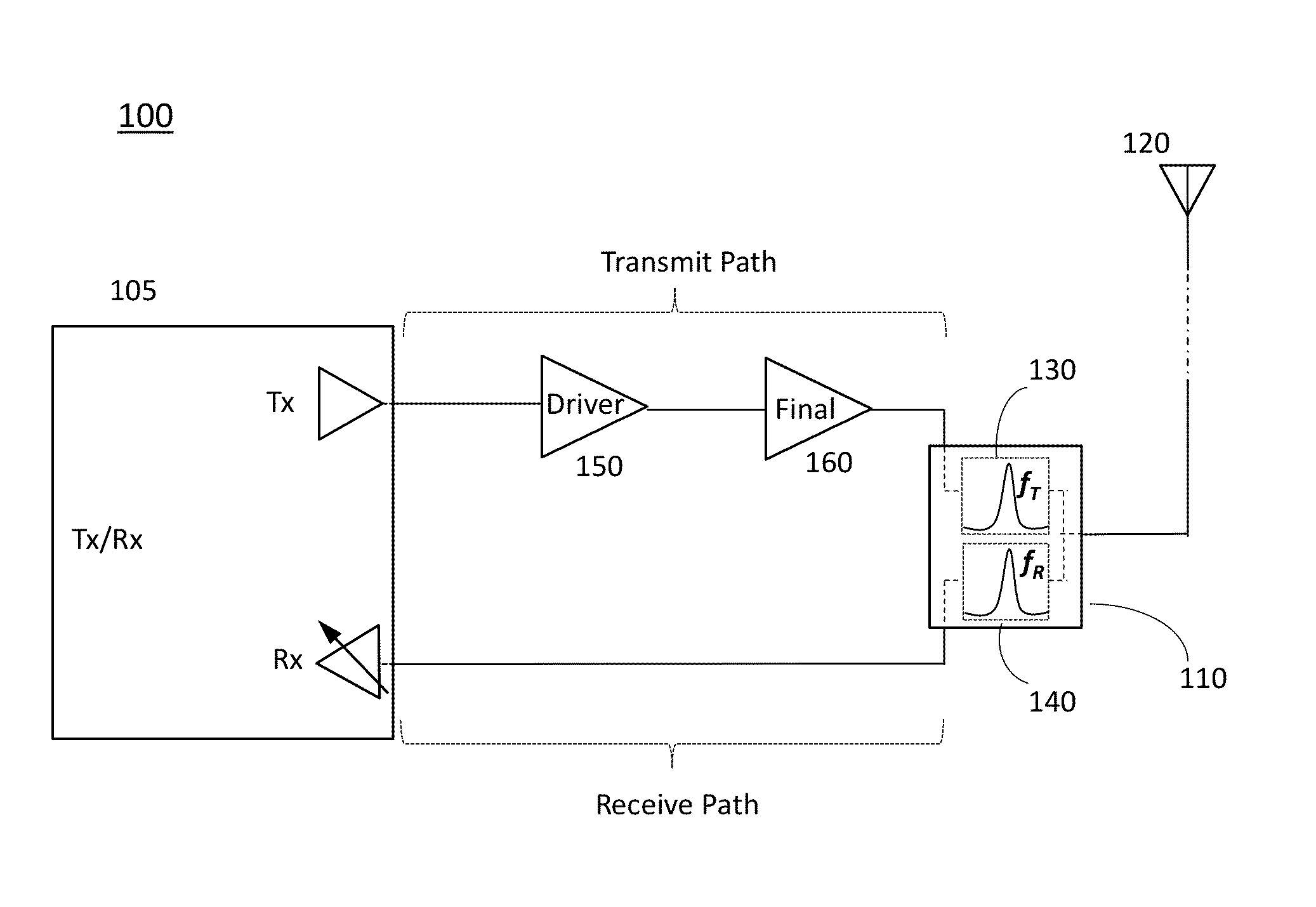
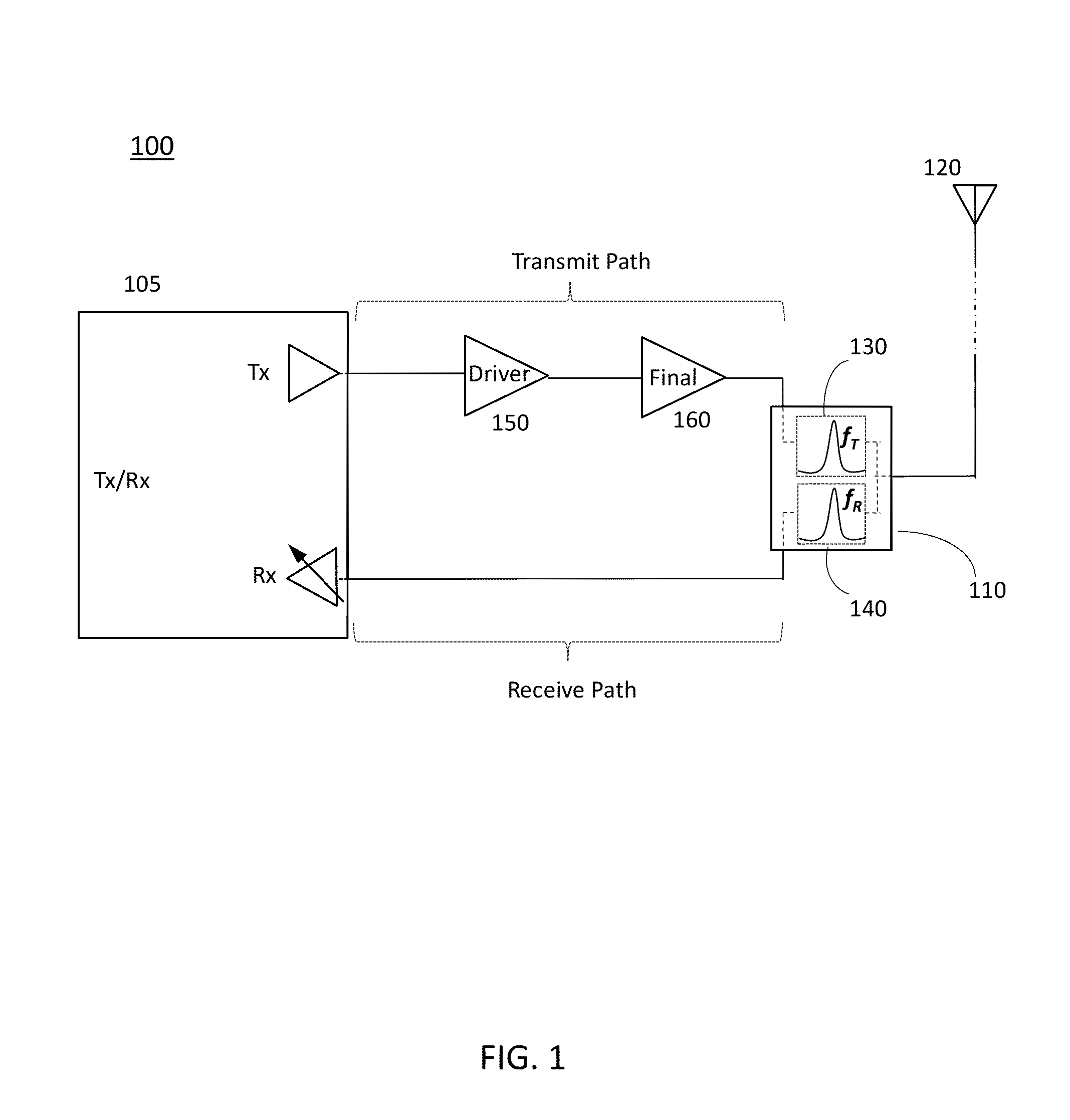
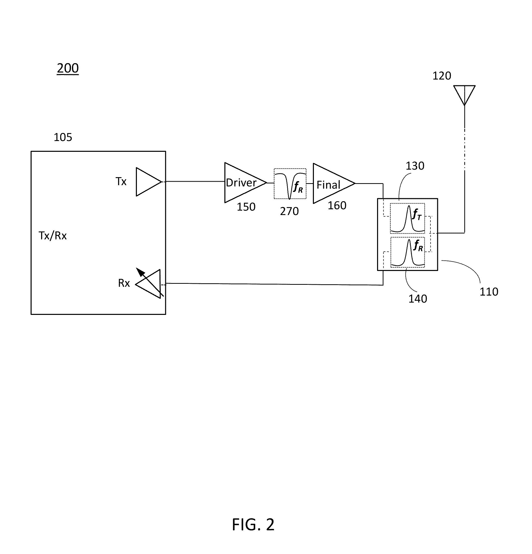
[0008]According to second aspect of the present disclosure, a method for reducing loss of a transmit RF signal in a duplexer unit of an radio frequency (RF) transmit/receive system, the method comprising: providing an RF transmit path comprising a plurality of cascaded amplifiers; inserting, in-between two amplifiers of the plurality of cascaded amplifiers, a first filter; based on the inserting, attenuating a receive frequency band and passi

Problems solved by technology

Radio frequency (RF) devices, such as cell phone transmitters, are becoming increasingly complex due to additional frequency bands, more complex modulation schemes, higher modulation bandwidths, and the introduction of data throughput improvement schemes such as simultaneous RF transmission and/or reception within a same or different, but closely spaced, bands or channels within a band (e.g. voice, data), and aggregate

Method used


Image

  • Devices and Methods for Duplexer Loss Reduction
  • Devices and Methods for Duplexer Loss Reduction
  • Devices and Methods for Duplexer Loss Reduction

Examples


Embodiment Construction

[0014]Throughout this description, embodiments and variations are described for the purpose of illustrating uses and implementations of the inventive concept. The illustrative description should be understood as presenting examples of the inventive concept, rather than as limiting the scope of the concept as disclosed herein.

[0015]The present disclosure describes electrical circuits in electronics devices (e.g., cell phones, radios) having a plurality of devices, such as for example, transistors (e.g., MOSFETs). Persons skilled in the art will appreciate that such electrical circuits comprising transistors can be arranged as amplifiers. As described in a previous disclosure (U.S. patent application Ser. No. 13 / 797,779, incorporated herein by reference in its entirety), a plurality of such amplifiers can be arranged in a so-called “scalable periphery” (SP) architecture of amplifiers where a total number (e.g., 64) of amplifier segments are provided. Depending on the specific requirem...


PUM


Abstract

Methods and devices are described for reducing transmit RF signal loss in a bi-directional RF transmit/receive system with a duplexer circuit. In one case a filter in a transmit path is used such as to reduce amplified noise in a receive frequency band.

Description

CROSS REFERENCE TO RELATED APPLICATIONS[0001]The present application is related to U.S. patent application Ser. No. ______ entitled “Methods for Increasing RF Throughput Via Usage of Tunable Filters” (Attorney Docket No. PER-099-PAP) filed on even date herewith and incorporated herein by reference in its entirety. The present application is also related to U.S. patent application Ser. No. ______ entitled “Integrated Tunable Filter Architecture” (Attorney Docket No. PER-115-PAP) filed on even date herewith and incorporated herein by reference in its entirety.[0002]The present application may be related to U.S. patent application Ser. No. 13 / 797,779 entitled “Scalable Periphery Tunable Matching Power Amplifier”, filed on Mar. 3, 2013, the disclosure of which is incorporated herein by reference in its entirety. The present application may also be related to International Application No. PCT / US2009 / 001358, entitled “Method and Apparatus for use in digitally tuning a capacitor in an inte...

Claims


Application Information

Patent Timeline
IPC IPC(8): H04B1/44H04B7/02
CPCH04B1/44H04B1/525H04B7/02H04B17/12H03F1/301H03F3/04H04B7/015H04B15/005H04B1/18H03F1/30H03F3/193H03F3/21H03F2200/451H03F2200/471H03F2200/555H03F3/195H03F3/213H03F2200/18H03F2200/456H04L27/20
Inventor NOBBE, DAN WILLIAM
Owner PSEMI CORP
Why Eureka
Try Eureka