Method for optimizing down fired reforming furnaces

a furnace and reforming furnace technology, applied in the field of optimizing down fired reforming furnaces, can solve the problems of excessive tube metal temperature, unfavorable combustion of down fired furnaces, and overheating of process tubes, so as to reduce burner flame deflection, and increase the burner discharge velocity

Active Publication Date: 2015-08-27
HONEYWELL INT INC
View PDF2 Cites 11 Cited by
  • Summary
  • Abstract
  • Description
  • Claims
  • Application Information

AI Technical Summary

Benefits of technology

[0021]The present invention relates to an improved method of steam methane reforming that will reduce deflections of burner flames in down-fired, multiple cell reforming furnaces.
[0022]The present invention serves to reduce the deflections in the burner flames, and to prevent the flow of hot combustion products from the outer cells to the center cells by creating a substantially uniform combustion gas and product discharge momentum between all cell burners—outer and center. This is accomplished by increasing the burner discharge veloc

Problems solved by technology

The combustion product flow patterns can be strong enough to cause deflections of the burner flames which ultimately leads to uneven heating of the process tubes and excessive tube metal temperatures.
The combustion product flow also causes the flames from the outer cell burners to bend toward the process tubes of the center cells and in many cases, the flames cause the m

Method used


Image

  • Method for optimizing down fired reforming furnaces
  • Method for optimizing down fired reforming furnaces
  • Method for optimizing down fired reforming furnaces

Examples


Embodiment Construction

[0026]The embodiments discussed herein are merely illustrative of specific manners in which to make and use the invention and are not to be interpreted as limiting the scope of the instant invention.

[0027]While the invention has been described with a certain degree of particularity, it is to be noted that many modifications may be made in the details of the invention's construction and the arrangement of its components without departing from the spirit and scope of this disclosure. It is understood that the invention is not limited to the embodiments set forth herein for purposes of exemplification.

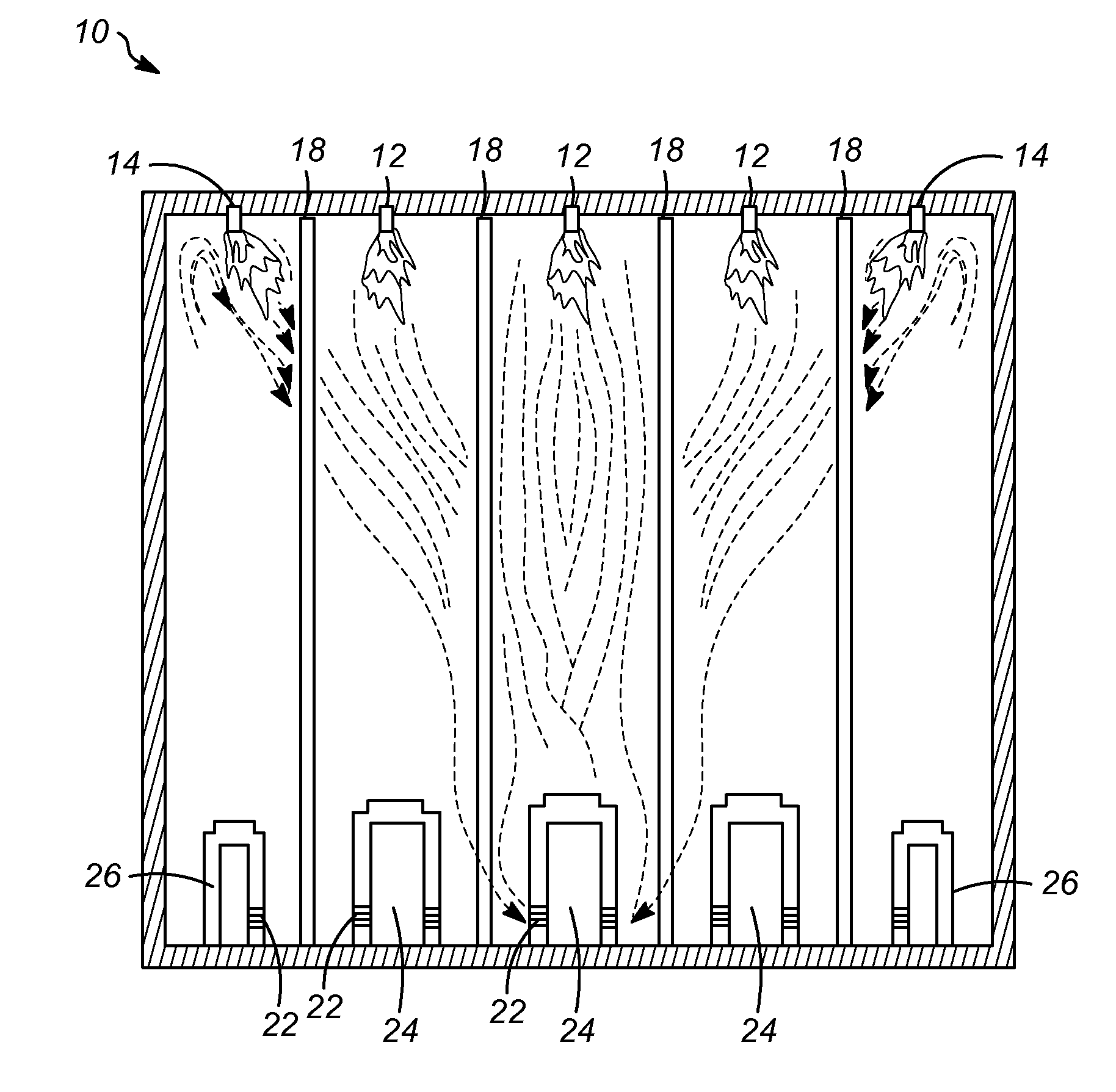
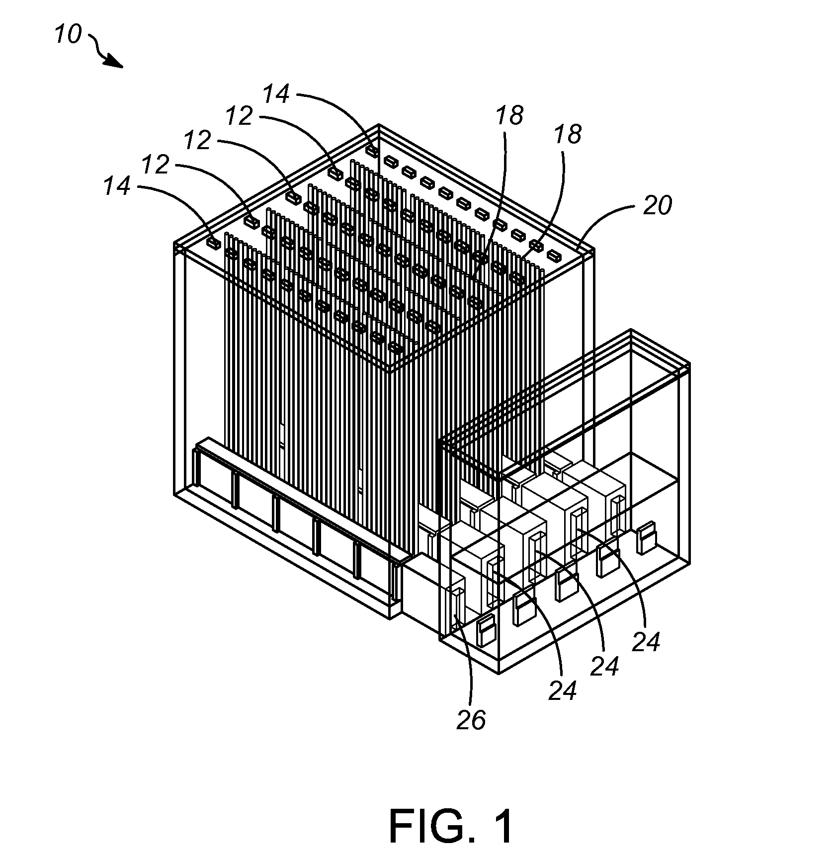
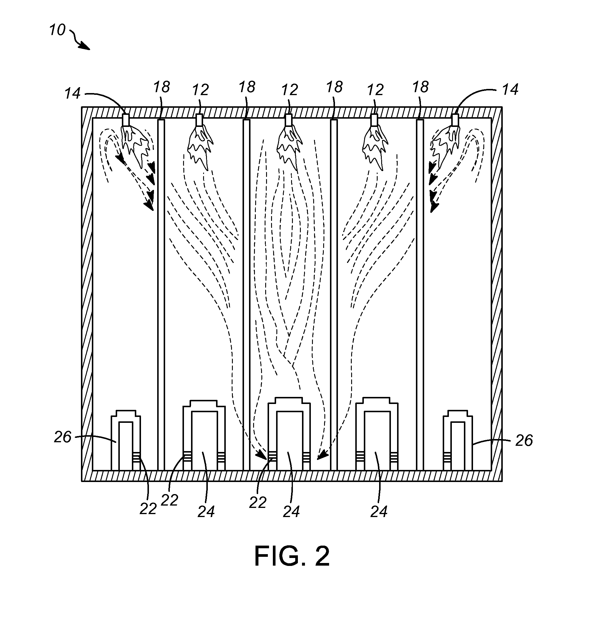
[0028]As shown in the drawings and understood by those skilled in the art, the method of steam methane reforming may commence in a down-fired, multiple cell reforming furnace to generate hydrogen and carbon monoxide from hydrocarbons and steam.

[0029]Referring now to FIG. 1, a perspective view of a down-fired, multiple cell furnace assembly 10 typically used in steam methane reforming is s...


PUM


Abstract

A method of optimizing steam methane reforming in a multiple cell, down-fired furnace. The method includes the steps of introducing hydrocarbons and steam to a plurality of catalyst filled process tubes, combusting gases through a plurality of center cell down-fired burners at a burner discharge velocity of V m/s, and a mass flow rate of 1 kg/s, combusting gases through outer cell down-fired burners at a burner discharge velocity of 1.5V-2V m/s and a mass flow rate of 0.5-0.65 kg/s, and finally discharging combustion products from the outer cell down-fired burners and the center cell down-fired burners at a substantially uniform momentum.

Description

CROSS REFERENCE TO RELATED APPLICATIONS[0001]Not Applicable.STATEMENT REGARDING FEDERALLY SPONSORED RESEARCH OR DEVELOPMENT[0002]Not Applicable.NAMES OF THE PARTIES TO A JOINT RESEARCH AGREEMENT[0003]Not Applicable.REFERENCE TO A SEQUENCE LISTING, A TABLE, OR A COMPUTER PROGRAM LISTING APPENDIX[0004]Not Applicable.BACKGROUND OF THE INVENTION[0005]1. Field of the Invention[0006]The present invention relates to an improved method of configuring and using a furnace. More specifically, the invention relates to an improved method to reduce deflections of burner flames in down-fired, steam methane reforming furnaces in order to optimize performance.[0007]2. Prior Art[0008]Steam methane reforming (“SMR”) processes for the production of synthesis gas are well known in the art. SMR involves a reaction of a hydrocarbon feedstock, typically in the form of natural gas, refinery gas, or naphtha, with steam at high temperatures. This reaction is in the presence of catalysts and produces a gas mix...

Claims


Application Information

Patent Timeline
IPC IPC(8): C01B3/38
CPCC01B2203/0255C01B3/386C01B3/384C01B2203/0233C01B2203/0816C01B2203/1241
Inventor MARTIN, RICHARD RAYMARTIN, MATTHEW
Owner HONEYWELL INT INC
Why Eureka
Try Eureka