Surface Property Inspection Apparatus, Surface Property Inspection System, and Surface Property Inspection Method

Active Publication Date: 2015-08-27
SINTOKOGIO LTD
View PDF6 Cites 11 Cited by
  • Summary
  • Abstract
  • Description
  • Claims
  • Application Information

AI Technical Summary

Benefits of technology

[0041]Using the claim 16 invention, the reference detector is furnished with a coil; a ferromagnetic core is disposed inside this coil rather than a reference test object, therefore

Problems solved by technology

Conventionally, evaluation of surface properties such as residual stress and hardness after surface processing of such products has been performed by sample destructi

Method used


Image

  • Surface Property Inspection Apparatus, Surface Property Inspection System, and Surface Property Inspection Method
  • Surface Property Inspection Apparatus, Surface Property Inspection System, and Surface Property Inspection Method
  • Surface Property Inspection Apparatus, Surface Property Inspection System, and Surface Property Inspection Method

Examples


first embodiment

Surface Property Test System: First Embodiment

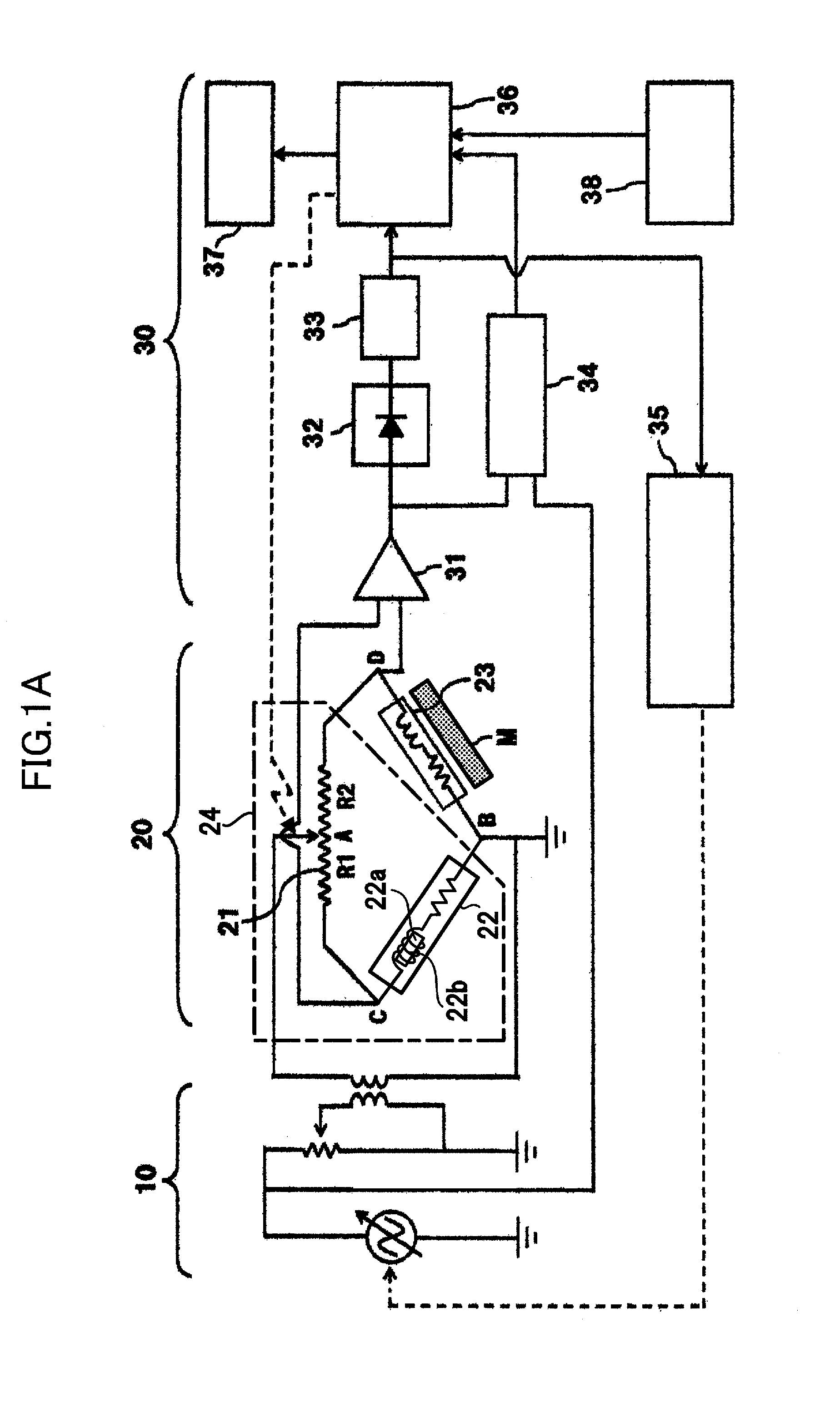
[0114]Next, including surface property inspection apparatus 1, we discuss a surface property evaluation system for evaluating the surface properties of an object under inspection either in-line or out-line in a surface processing step using a shot-peening apparatus for performing shot-peening as surface processing. As shown in FIGS. 4A˜4D and FIGS. 5A˜5D, surface property evaluation system 100 is furnished with a surface processing apparatus 110 for performing surface processing of object under inspection M, a first transport mechanism 120 comprising a cylinder, a second transport mechanism 121 comprising a transport arm, a third transport mechanism 122 comprising a conveyor, and a test detector transport mechanism 123 comprising a cylinder. Note that in FIGS. 4A˜4D and FIGS. 5A˜5D, plan views and side views are shown at top and bottom. In the plan views of FIGS. 4A, 4B, and 5D, a diagram of inspection detector 23 is omitted. Also, inspe...

second embodiment

Surface Property Test System: Second Embodiment

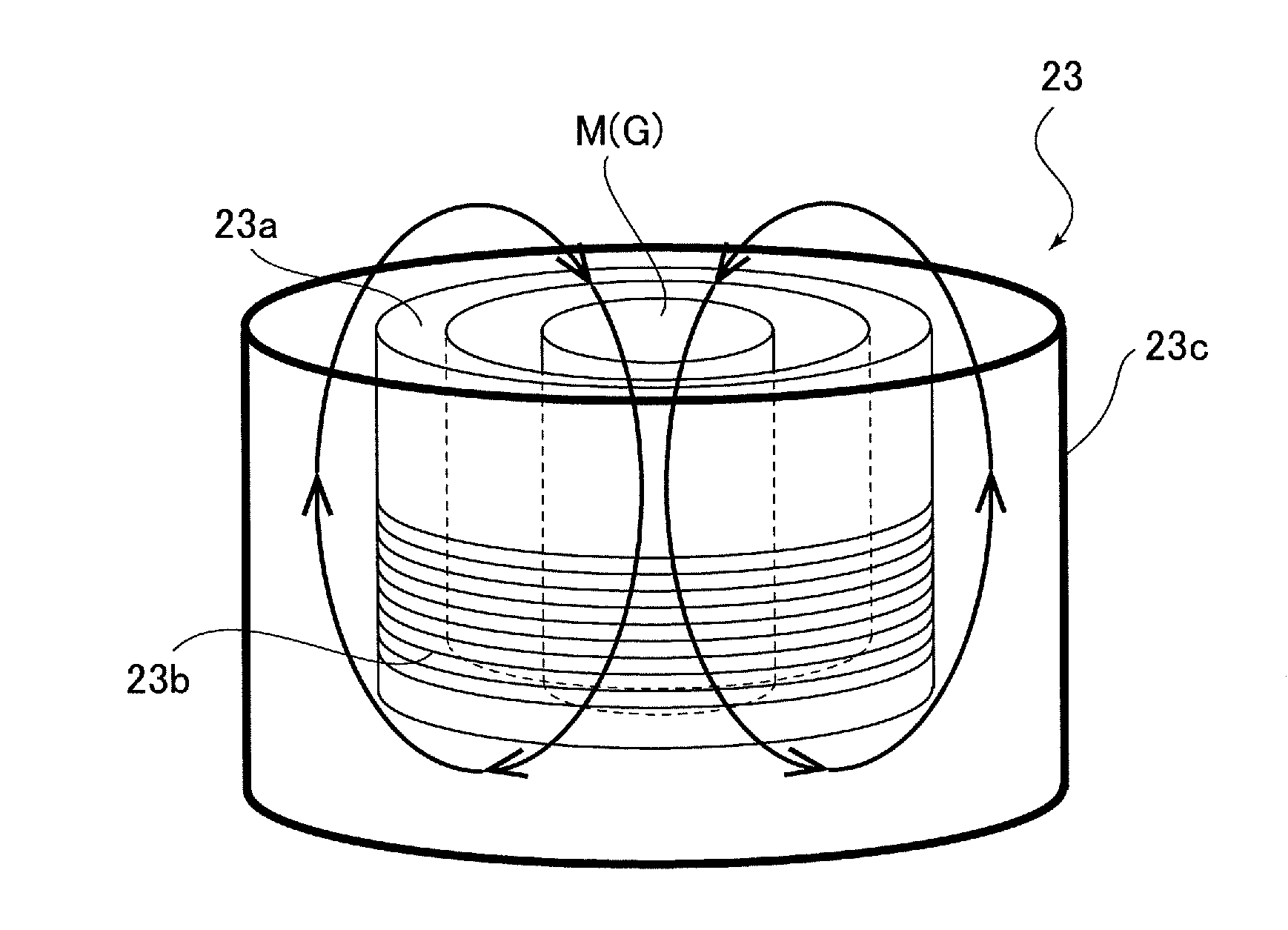
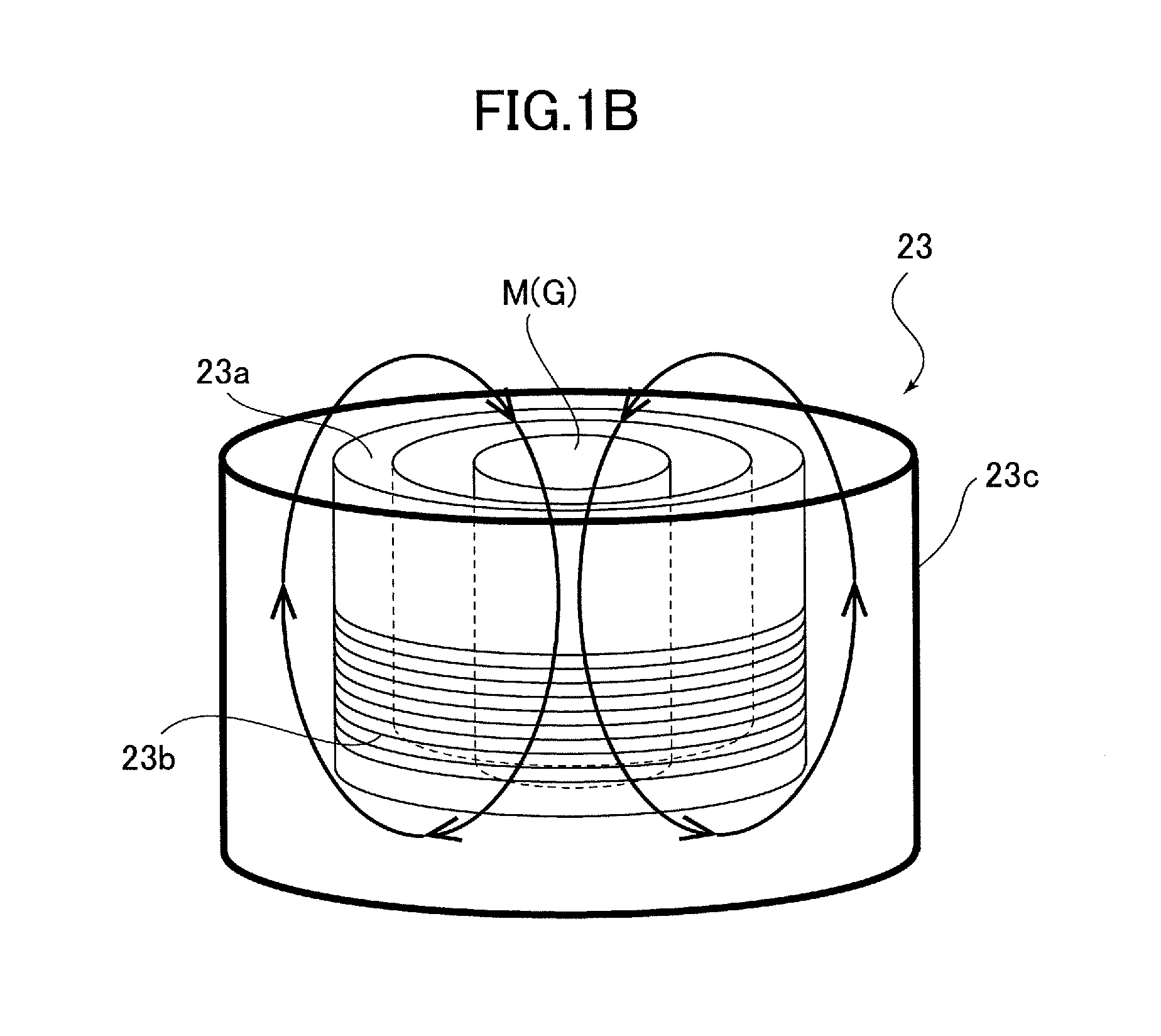
[0131]As shown in FIGS. 8A and 8B, a surface property evaluation system 200 is built into inspection detector 23 inside processing chamber 114 of surface processing apparatus 110. Note that in FIGS. 8A and 8B, a diagram of the mechanism for transporting object under inspection M to surface processing apparatus 110, such as second transport mechanism 121 or third transport mechanism 122, is omitted.

[0132]FIG. 8A shows the state in which shot-peening is being applied to gear G. To explain the structure and operation of detector protective panel 118, in FIG. 8A we include a plan view of the region close to detector protective panel 118 and a front elevation seen from the left side of the figure. Inspection detector 23 is connected to cylinder 119, which transports inspection detector 23 and is a moving mechanism for positioning gear G at evaluation position Ts inside coil 23b, and is disposed above gear G, coaxial with the gear G shaft. Ou...

embodiments

[0146]An object under inspection in which a gas-carburized cylindrical SCr420 material is shot-peened on its side surface is compared using the surface property inspection method of the present invention with an inspection method in which 7 samples of differing coverage levels are prepared. Coverage here refers to the post-surface processing surface hit mark percentage, and indicates that the large the coverage, the higher is the surface processing density. We varied the inspection environment surrounding temperature from 10˜40° C., performed an inspection, and compared outputs.

[0147]FIG. 10A is a graph showing the rate of change in amp output caused by surrounding temperature when inspecting a sample with 100% coverage using a reference surrounding temperature of 10° C.; the vertical axis is output change %, and the y axis is the surrounding temperature. It can be seen from this graph that there is less output change caused by temperature with the surface property inspection method...


PUM

PropertyMeasurementUnit
Temperatureaaaaaaaaaa
Surface propertiesaaaaaaaaaa
Areaaaaaaaaaaa

Abstract

To provide a surface property inspection apparatus, surface property inspection system, and surface property inspection method capable of inspecting the surface processing state of processed material subjected to surface processing such as shot-peening, heat treatment, or nitriding with high accuracy and low vulnerability to temperature changes in the inspection environment. Surface property inspection apparatus is furnished with a AC power supply, a AC bridge circuit, and an evaluation device; AC bridge circuit comprises variable resistor with which distribution ratio γ is variable, reference detector, and inspection detector. Inspection detector is furnished with a coil wound so as to oppose the surface property inspection region of object under inspection M, and by supplying AC power from AC power supply to coil, an eddy current is excited in object under inspection M. Thus the magnetic properties of object under inspection M can be detected, and inspection of surface properties based on the output signal from AC power supply is possible.

Description

RELATED APPLICATIONS[0001]This application is a continuation application of PCT / JP2014 / 054100 having an international filing date of Feb. 14, 2014, which claims priority to JP 2013-113694 filed May 30, 2013, the entire contents of which are incorporated herein by reference.TECHNICAL FIELD[0002]The present invention pertains to a surface property inspection apparatus for non-destructive inspection of the surface processing state of processed material subjected to surface processing such as shot-peening, heat treatment, or nitriding.BACKGROUND ART[0003]Surface processing such as surface hardening or shot-peening by heat treatment, nitriding, and the like is applied to steel parts such as gears and shafts used as automobile parts, etc. to improve friction resistance, fatigue strength, and the like.[0004]Conventionally, evaluation of surface properties such as residual stress and hardness after surface processing of such products has been performed by sample destructive inspection. This...

Claims


Application Information

Patent Timeline
IPC IPC(8): G01N27/90
CPCG01N27/9006G01N27/9046C21D7/06C21D11/00
Inventor MAKINO, YOSHIYASUKAGA, HIDEAKI
Owner SINTOKOGIO LTD
Why Eureka
Try Eureka