
Display Having Selective Portions Driven with Adjustable Refresh Rate and Method of Driving the Same

Active Publication Date: 2015-08-27
LG DISPLAY CO LTD
View PDF4 Cites 92 Cited by
  • Summary
  • Abstract
  • Description
  • Claims
  • Application Information

AI Technical Summary

Benefits of technology

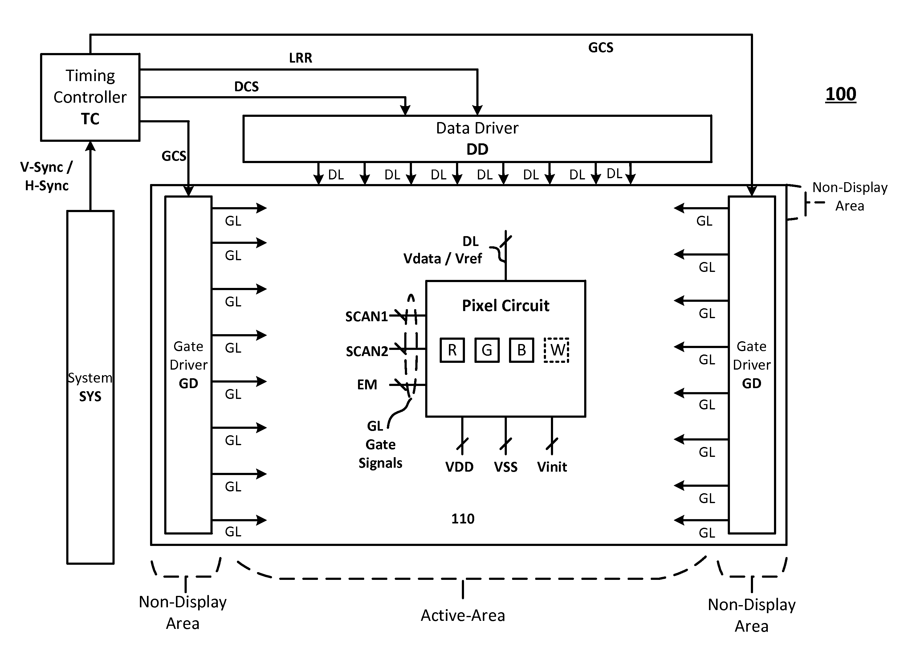
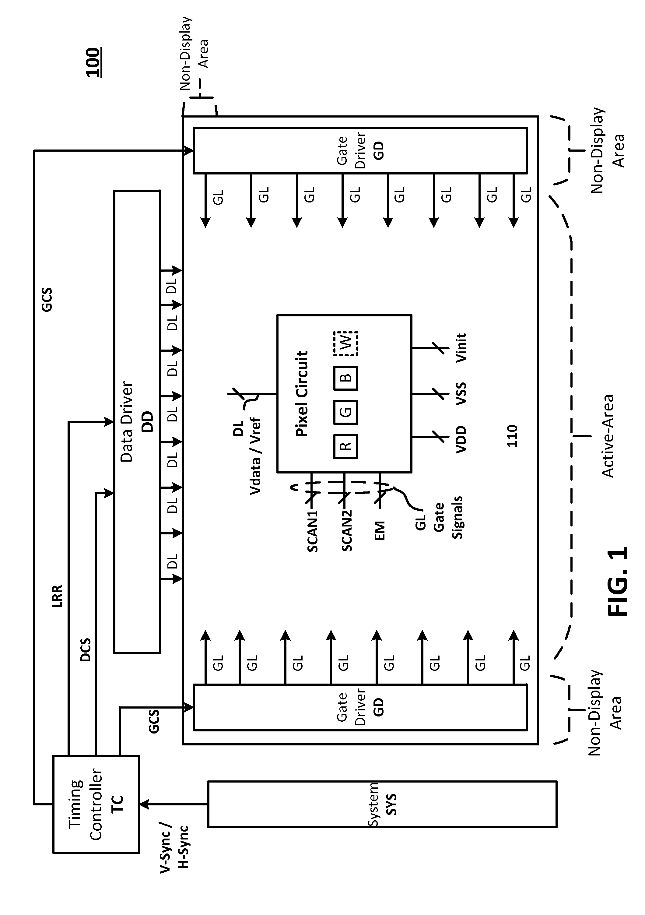
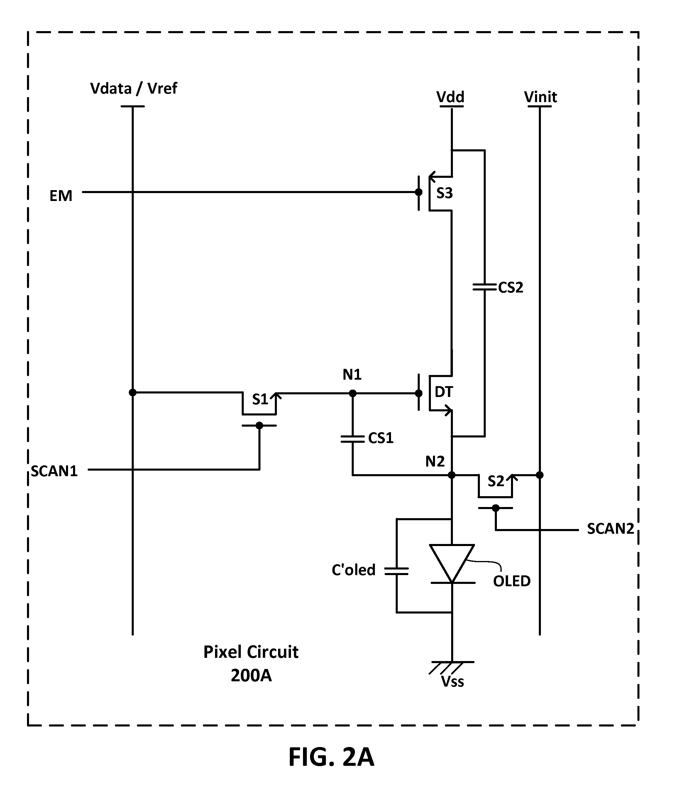
The present patent is directed to a TFT backplane with driving circuits for a display and a method of driving the same to reduce power consumption. The driving circuit and method may turn off signals to some pixels in the display for certain image frames, so image data is processed at a lower speed refresh mode. Additionally, the patent describes a thin-film-transistor backplane that has at least one TFT with oxide or poly-silicon active layer. The backplane includes a display area with a matrix of pixels operated by a pixel circuit and a non-display area with at least one driving circuit configured to drive the pixel circuits at different frequencies. The technical effect of the present patent is to provide a more efficient and effective way of driving a display with reduced power consumption and improved low refresh mode operation.

Problems solved by technology

Lowering the frame rate for at least some part of the display can result in extra power savings, which is one of the most critical issues for mobile devices.
However, operating the display with the low refresh rate mode described above may not be feasible with a TFT backplane employing a single type of TFTs.
However, sensing of the Vth can take significantly longer with an oxide TFT (e.g., as much as 7 times of an LTPS TFT).
Also, the size of the oxide TFTs is larger than LTPS TFTs, and using oxide TFTs to implement the driving circuit on a TFT backplane can increase the size of the non-display area that needs to be covered by the bezel.
Most importantly, implementing the driving circuit entirely by using the oxide TFTs may not provide sufficient driving frequency during the normal refresh mode of the display.

Method used


Image

  • Display Having Selective Portions Driven with Adjustable Refresh Rate and Method of Driving the Same
  • Display Having Selective Portions Driven with Adjustable Refresh Rate and Method of Driving the Same
  • Display Having Selective Portions Driven with Adjustable Refresh Rate and Method of Driving the Same

Examples


Embodiment Construction

[0034]Various features and advantages described in the present disclosure will be more clearly understood from the following description with reference to the accompanying drawings. Note that the accompanying drawings are merely illustrative and may not be drawn to scale for easier explanation. Also, components having the same or similar function may be denoted by the same reference symbols / numeral throughout the drawings for describing various embodiments. The descriptions of the same or similar components may be omitted.

[0035]It will be understood that when an element as a layer, region or substrate is referred to as being “on” or “over” another element, it can be directly on the other element or intervening elements may also be present. In contrast, when an element is referred to as being “directly on” or “directly over” another element, there are no intervening elements present. It will also be understood that when an element is referred to as being “connected” or “coupled” to a...


PUM


Abstract

There is provided a TFT backplane having at least one TFT with oxide active layer and at least one TFT with poly-silicon active layer. In the embodiments of the present disclosure, at least one of the TFTs implementing the circuit of pixels in the active area is an oxide TFT (i.e., TFT with oxide semiconductor) while at least one of the TFTs implementing the driving circuit next to the active area is a LTPS TFT (i.e., TFT with poly-Si semiconductor).

Description

[0001]This application claims priority to U.S. provisional patent application No. 61 / 944,469, filed on Feb. 25, 2014, which is hereby incorporated by reference in its entirety.BACKGROUND[0002]1. Technical Field[0003]The present invention relates to a display, and more particularly, to a display capable of driving selective portions with adjustable refresh rate to reduce power consumption of the display and to improve touch scan capability of the display, as well as a method of driving such display.[0004]2. Description of the Related Art[0005]Flat panel display (FPD) are employed in various electronic devices such as mobile phones, tablets, notebook computers as well as televisions and monitors. Examples of the FPD includes a liquid crystal display (LCD), a plasma display panel (PDP), an organic light emitting diode (OLED) display as well as an electrophoretic display (EPD).[0006]Generally, pixels of the FPDs are arranged in a matrix form, and each pixel generates light (luminescence...

Claims


Application Information

Patent Timeline
IPC IPC(8): G09G3/20G09G3/32
CPCG09G3/2092G09G3/3233G09G3/3291G09G2330/023G09G2310/0272G09G2310/0262G09G2320/0252G09G2300/0814H01L27/1225H01L27/1251G06F3/0418G09G3/3241G09G3/3648
Inventor KIM, HYOUNG-SUCHO, NAMWOOKKIM, TAEHWANLEE, JAEMYON
Owner LG DISPLAY CO LTD
Learn More