Antenna device

an antenna and antenna technology, applied in the field of antenna devices, can solve problems such as difficult to ensure sufficient isolation, and achieve the effects of improving radiation efficiency, improving isolation, and small correlation coefficien

Active Publication Date: 2015-08-27
MURATA MFG CO LTD
View PDF4 Cites 18 Cited by
  • Summary
  • Abstract
  • Description
  • Claims
  • Application Information

AI Technical Summary

Benefits of technology

[0030]Providing the continuity structure between the first driven element and the second driven element makes it possible to improve isolation between the first driven element and the second driven element and achieve a small correlation coefficient. Allowing the first conductor plate and the second conductor plate to perform a dipole operation can improve radiation efficiency. With the first parasitic element and the second parasitic element, it is possible to improve radiation efficiency, achieve a multi-resonant state, and widen the operation bandwidth. When the first driven element has a surface facing the second conductor plate at any position within a range of motion of the second housing, it is possible to ensure stable electromagnetic coupling between the first driven element and the second conductor plate.

Problems solved by technology

With a conventional antenna structure, it is difficult to ensure sufficient isolation.

Method used


Image

  • Antenna device
  • Antenna device
  • Antenna device

Examples


first embodiment

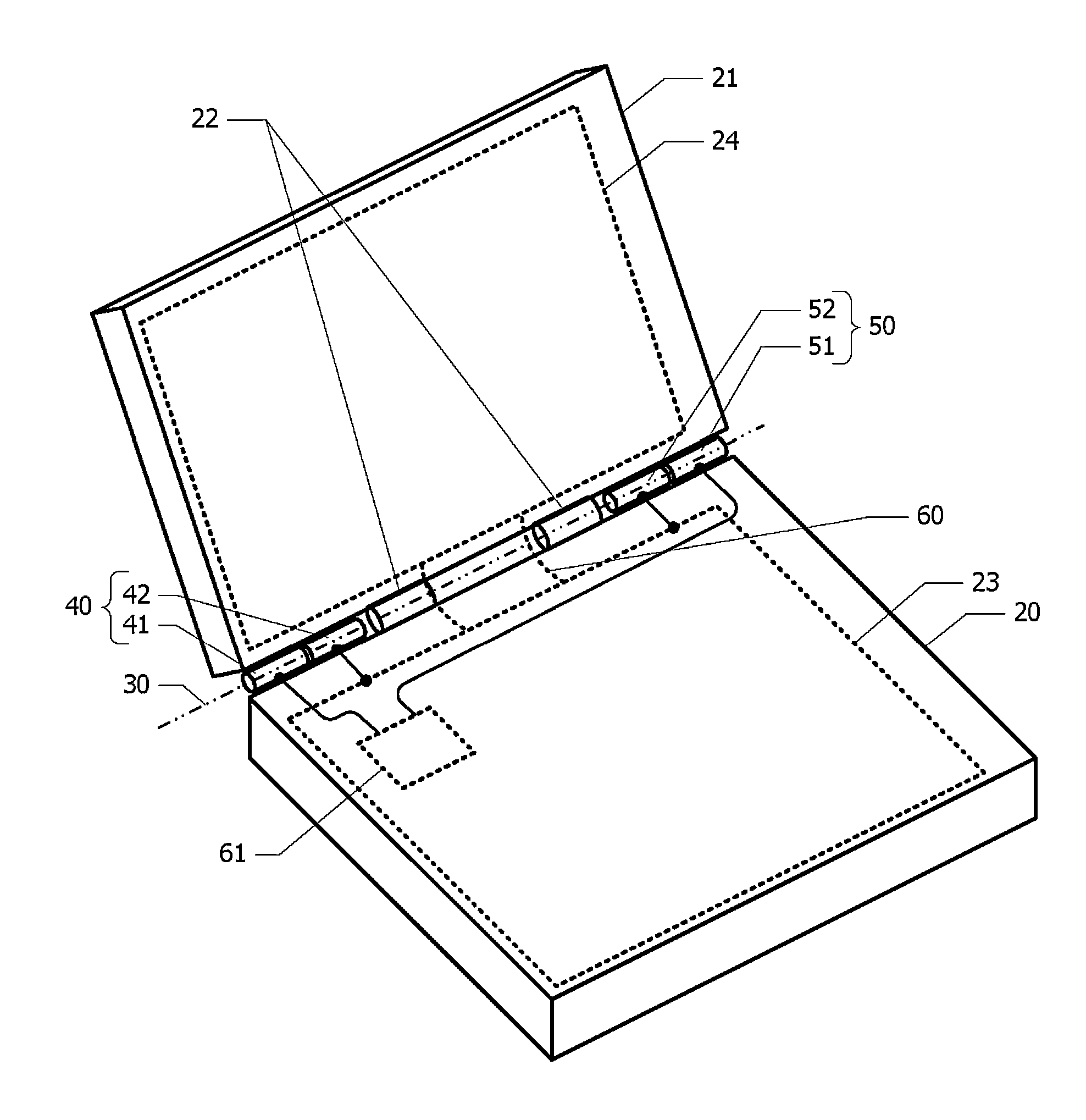
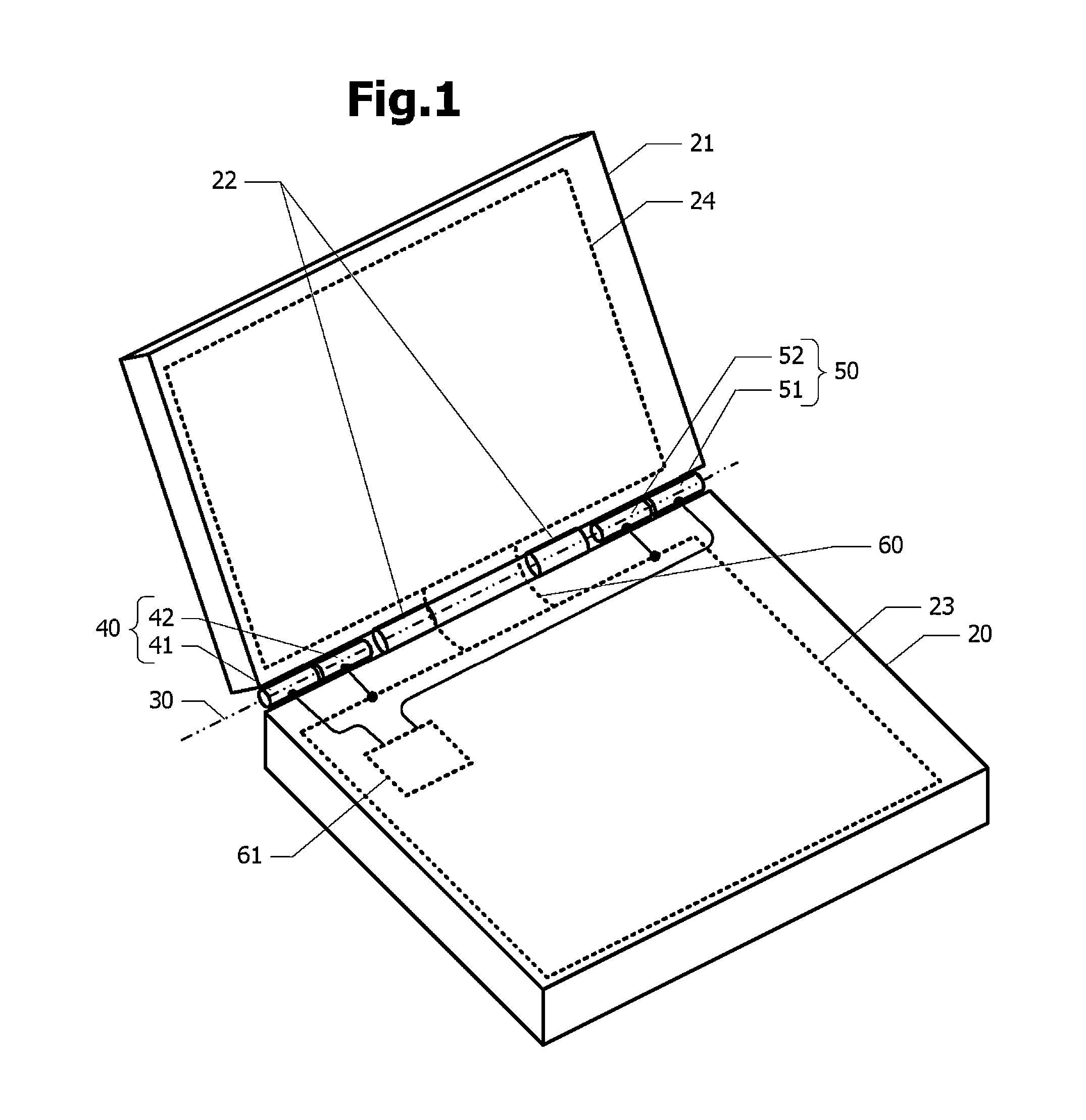
[0048]FIG. 1 is a schematic perspective view of an electronic apparatus including an antenna device according to a first embodiment. A second housing 21 is openably and closably attached to a first housing 20 by rotation mechanisms 22. For example, the first housing 20 contains a keyboard and the second housing 21 contains a liquid crystal panel. The rotation mechanisms 22 include, for example, hinges. The first housing 20 contains a first conductor plate 23, and the second housing 21 contains a second conductor plate 24. When the first housing 20 is made of an insulating material, such as resin, the first conductor plate 23 is disposed inside the first housing 20. When the first housing 20 is made of a conductive material, such as metal, the first housing 20 also serves as the first conductor plate 23. Similarly, the second housing 21 contains or serves as the second conductor plate 24.

[0049]A first driven element 41, a first parasitic element 42, a second driven element 51, and a ...

second embodiment

[0070]FIG. 8A is a perspective view of an antenna device according to a second embodiment. Hereinafter, differences from the first embodiment will be described, and the description of the same configuration will be omitted. Along the rotation axis 30, the rotation mechanism 22, the first parasitic element 42, and the first driven element 41 are arranged in this order from the center to the left, whereas the rotation mechanism 22, the second parasitic element 52, and the second driven element 51 are arranged in this order from the center to the right.

[0071]FIG. 8B is a schematic diagram of the rotation mechanisms 22 and their vicinity. The rotation mechanisms 22 each include a first member 22A secured to the first housing 20 and a second member 22B secured to the second housing 21. The first member 22A and the second member 22B are made of a conductive material, such as metal. The first member 22A is electrically connected to the first conductor plate 23, and the second member 22B is...

third embodiment

[0072]FIG. 9A is a perspective view of an antenna device according to a third embodiment. Hereinafter, differences from the first embodiment will be described, and the description of the same configuration will be omitted. Along the rotation axis 30, the continuity structure 60 is disposed in the center, the rotation mechanism 22 and the first driven element 41 are arranged in this order from the center to the left, and the rotation mechanism 22 and the second driven element 51 are arranged in this order from the center to the right.

[0073]FIG. 9B is a schematic diagram of the first driven element 41, the rotation mechanism 22, and their vicinity. The first driven element 41 is connected to the high-frequency circuit 61. The rotation mechanism 22 includes a first member 22C secured to the first housing 20 and a second member 22D secured to the second housing 21. At least part of the first member 22C is made of a conductive material, such as metal. The conductive part of the first mem...


PUM


Abstract

A first housing includes a first conductor plate, and a second housing includes a second conductor plate. A rotation mechanism openably and closably attaches the second housing to the first housing. A first driven element and a second driven element are arranged along a rotation axis of the rotation mechanism. Between the first driven element and the second driven element, a continuity structure intersects the rotation axis to establish direct-current or high-frequency continuity between the first conductor plate and the second conductor plate. An antenna device can be provided which can ensure sufficient isolation between a plurality of driven elements.

Description

CROSS-REFERENCE TO RELATED APPLICATIONS[0001]The present application is a continuation of PCT / JP2013 / 071549 filed Aug. 8, 2013, which claims priority to Japanese Patent Application No. 2012-248927, filed Oct. 13, 2012, the entire contents of each of which are incorporated herein by reference.FIELD OF THE INVENTION[0002]The present invention relates to an antenna device that includes a rotation mechanism configured to openably and closably couple a pair of housings, and antenna elements arranged along a rotation axis of the rotation mechanism.BACKGROUND OF THE INVENTION[0003]An antenna structure in which an antenna element is disposed on a hinge portion of a folding mobile terminal is known. In an antenna structure disclosed in Patent Document 1, an antenna element for a non-contact IC card is disposed on a cylindrical hinge portion. With this structure, stable wireless communication with a reader and writer can be ensured on both sides of a mobile terminal.[0004]In an antenna struct...

Claims


Application Information

Patent Timeline
Patent Type & Authority Applications(United States)
IPC IPC(8): H01Q1/22H01Q5/378H01Q5/10
CPCH01Q5/378H01Q1/2266G06F1/1616G06F1/1681G06F1/1698H01Q1/44H01Q9/40H01Q21/28
Inventor ONAKA, KENGOTANAKA, HIROYA
Owner MURATA MFG CO LTD
Why Eureka
Try Eureka