Method and device for wall mounting flat panel monitor and storing associated audio/video components

a flat panel monitor and audio/video technology, which is applied in the direction of casings/cabinets/drawers, furniture parts, electrical appliances, etc., can solve the problems of limiting the possible placement location of flat panel monitors, cumbersome installation of flat panel monitor mounting devices, and inability to address the typical need to accommodate associated components, etc., to facilitate mounting flat panel monitors, increase structural rigidity and integrity, and facilitate modification or modification

Active Publication Date: 2015-09-03
INNOVATIVE AMERICANS
View PDF25 Cites 4 Cited by
  • Summary
  • Abstract
  • Description
  • Claims
  • Application Information

AI Technical Summary

Benefits of technology

[0009]Yet another object of the present invention is to provide a mounting device which can be either directly mounted to the wall or other support structure or mounted to a conventional mounting device which is directly mounted to the wall or other support structure and facilitate mounting a flat panel monitor to a desired wall or other support structure.
[0010]A further object of the present invention is to provide a mounting device in which the relative spacing between the front and rear panels of the mounting device can be readily altered or modified, with respect to one another, so as to provide the mounting device with a manual adjustment feature which provides the flat panel monitor with a desired tilt of from a few degrees or so (3.5 degrees) to as much as 10° of tilt,
[0011]A still further object of the present invention is to provide a mounting device which comprises a housing which is sufficiently closed on five sides thereof, namely, the front and rear sides, the left and the right sides, and the bottom side, and only opened on the top side thereof so as to facilitate access to the internal cavity of the mounting device and the peripheral electronic device(s), component(s) or accessory located therein to facilitate ease of installing or removing a desired peripheral electronic device(s), component(s) or accessory to and from the internal cavity of the mounting device.
[0012]Another object of the present invention is to provide the tabs of the front and rear panels with mating locking features so that adjacent tabs, one overlapped with one another, can interlock with one another and such interlocking feature of the tabs further increases the structural rigidity and integrity of the housing formed by the two mating panels of the mounting device.
[0013]Another object of the present invention is to provide a mounting device having L-shaped brackets which are connected to the rear panel of the mounting device and which support a shelf for supporting a further peripheral electronic device(s), component(s) or accessory. The shelf is adjustable with respect to the mounting device and enables easy access to the further peripheral electronic device(s), component(s) or accessory.
[0014]A further object of the present invention is to provide a mounting device having universal mounting channels so as to facilitate accommodating flat panel monitors of different sizes. The channels further enable lateral adjustment of the flat panel monitor with respect to the mounting device.

Problems solved by technology

However, such mounting devices for a flat panel monitor are generally cumbersome to install and typically do not provide space, e.g., an internal cavity or recess, for any peripheral electronic device or accessory, including but are not limited to, a HD box(es), a video network reception box(es) (i.e., Roku), a cable TV satellite box(es), a video game device(s) or console(s), e.g., a PlayStation® console or an X-box® console, a DVD player(s), a cable TV box(es), a Blu-ray player(s), a Wired or Wireless Internet Reception Device, etc.
While these devices are adequate in their ability to support a flat panel monitor, they do not address the typical need to accommodate associated components typically used in conjunction with a flat panel monitor, as discussed above.
Further, the need for additional, external, accessory containment limits the possible placement location of the flat panel monitor as such additional wall and / or floor space must be considered.
Further, a number of wires and cables are generally required in order to connect the flat panel monitor with the peripheral electronic component(s) or accessory and such wiring can be unsightly and / or objectionable.

Method used


Image

  • Method and device for wall mounting flat panel monitor and storing associated audio/video components
  • Method and device for wall mounting flat panel monitor and storing associated audio/video components
  • Method and device for wall mounting flat panel monitor and storing associated audio/video components

Examples


Embodiment Construction

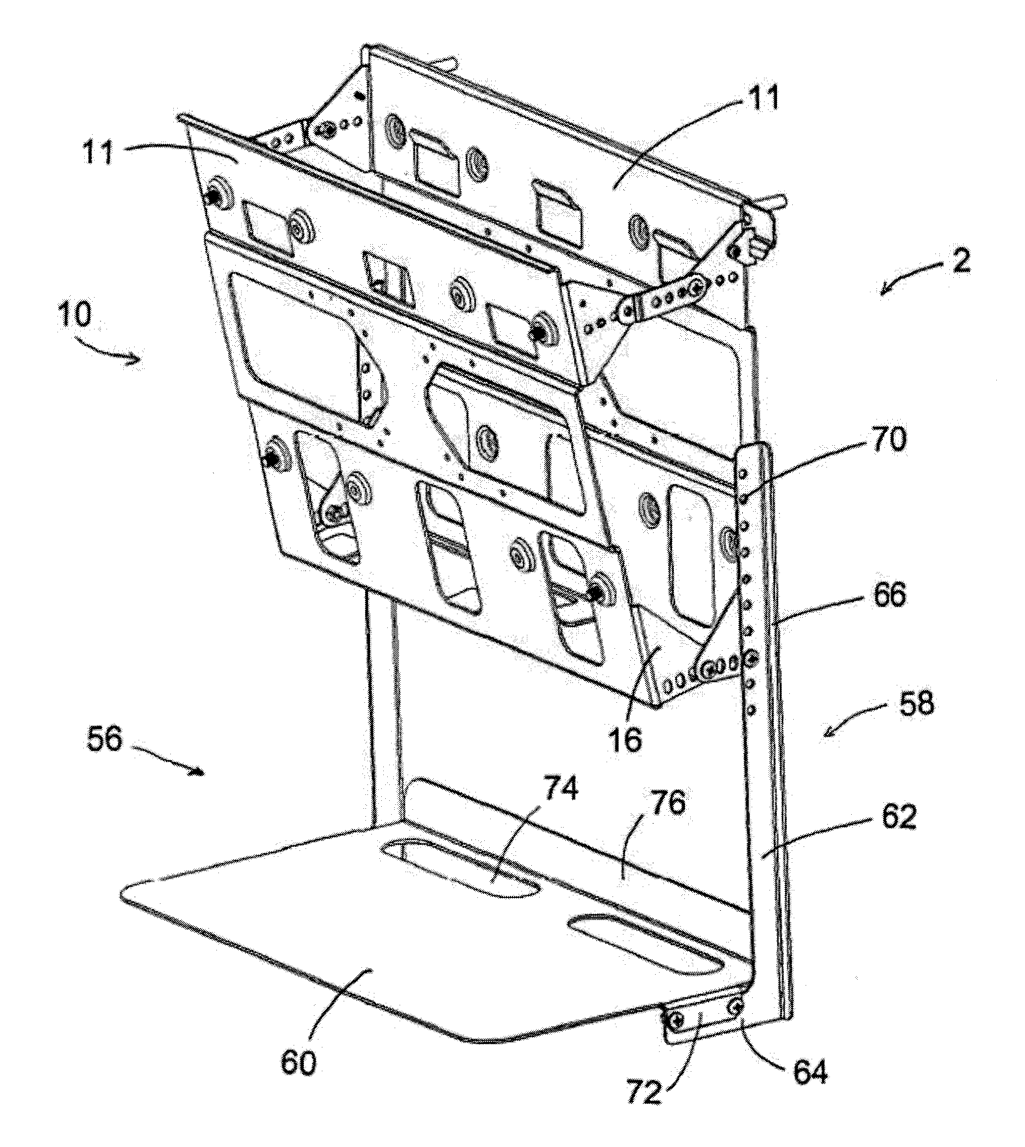
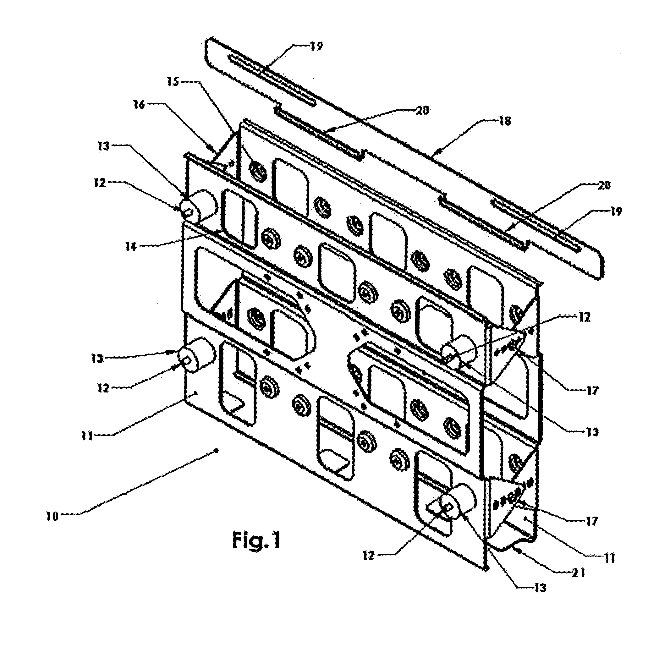
[0047]Turning now to FIG. 1, a brief description concerning the various components of the mounting device 2, according to present invention, will now be briefly discussed. As shown therein, the mounting device 2 comprises a generally rigid housing 10 which is formed by mating front and rear panels 11 each of which contains one or more horizontal supports and retaining features 21 which extend from one of the panels 11 toward the other panel and form a bottom side or base of the housing 10. Once the front and the rear panels 11 are assembled together with one another, as described below, and two sets of opposed pairs of end interconnection tabs 16 are securable to the mating tabs 16 of the other panel 11 by conventional hardware 17, a rigid housing 10, as shown in FIG. 1, is formed that will contain a desired peripheral electronic device(s), component(s) or accessory as will be described in further detail below. The horizontal support and retaining features 21 and the mating tabs 16 ...


PUM

PropertyMeasurementUnit
lengthaaaaaaaaaa
widthaaaaaaaaaa
lengthaaaaaaaaaa

Abstract

A mounting device for a flat panel monitor. The mounting device comprises a front panel and a mating second rear panel for connection with one another to form a housing. At least the front panel has a plurality of mounting apertures therein for securing the housing to a desired flat panel monitor while the rear panel has a mounting mechanism which facilitates attachment of the housing to a desired support surface. An internal recess is formed between the front panel and the rear panel, when assembled with one another, and the internal recess is sized for accommodating and retaining at least one peripheral electronic device therein.

Description

FIELD OF THE INVENTION[0001]The present invention relates to a novel mounting device for accommodating various electronic components and / or accessories between the rear surface of a television and a desired supporting wall or other structure. More particularly, the present invention relates to attaching and supporting a flat panel monitor to a desired wall and / or other supporting structure with a mounting device which includes an internal recess for supporting and containing associated peripheral components and / or accessories typically used in conjunction with a flat panel monitor.BACKGROUND OF THE INVENTION[0002]A variety of different devices are currently available to facilitate mounting and / or supporting a flat TV panel monitor to a wall or some other supporting surface. However, such mounting devices for a flat panel monitor are generally cumbersome to install and typically do not provide space, e.g., an internal cavity or recess, for any peripheral electronic device or accessor...

Claims


Application Information

Patent Timeline
Patent Type & Authority Applications(United States)
IPC IPC(8): A47B97/00H05K5/02A47B96/02
CPCA47B97/001H05K5/0217H05K5/0213A47B96/02F16M11/10F16M13/02F16M2200/08Y10T29/49947
Inventor DOWLING, JAMESFECTEAU, MARK
Owner INNOVATIVE AMERICANS
Why Eureka
Try Eureka