
Brake System for a Vehicle

a technology for brake actuators and vehicles, applied in the direction of braking systems, rotary clutches, fluid couplings, etc., can solve the problems of increasing the integration problem of braking equipment, requiring a relatively large amount of space within the running gear, and almost equally short strokes of the brake actuators over the life of friction elements, etc., to achieve compact braking, improve the safety of the operation, and simplify the approval process

Inactive Publication Date: 2015-09-03
BOMBARDIER TRANSPORTATION GMBH
View PDF2 Cites 0 Cited by
  • Summary
  • Abstract
  • Description
  • Claims
  • Application Information

AI Technical Summary

Benefits of technology

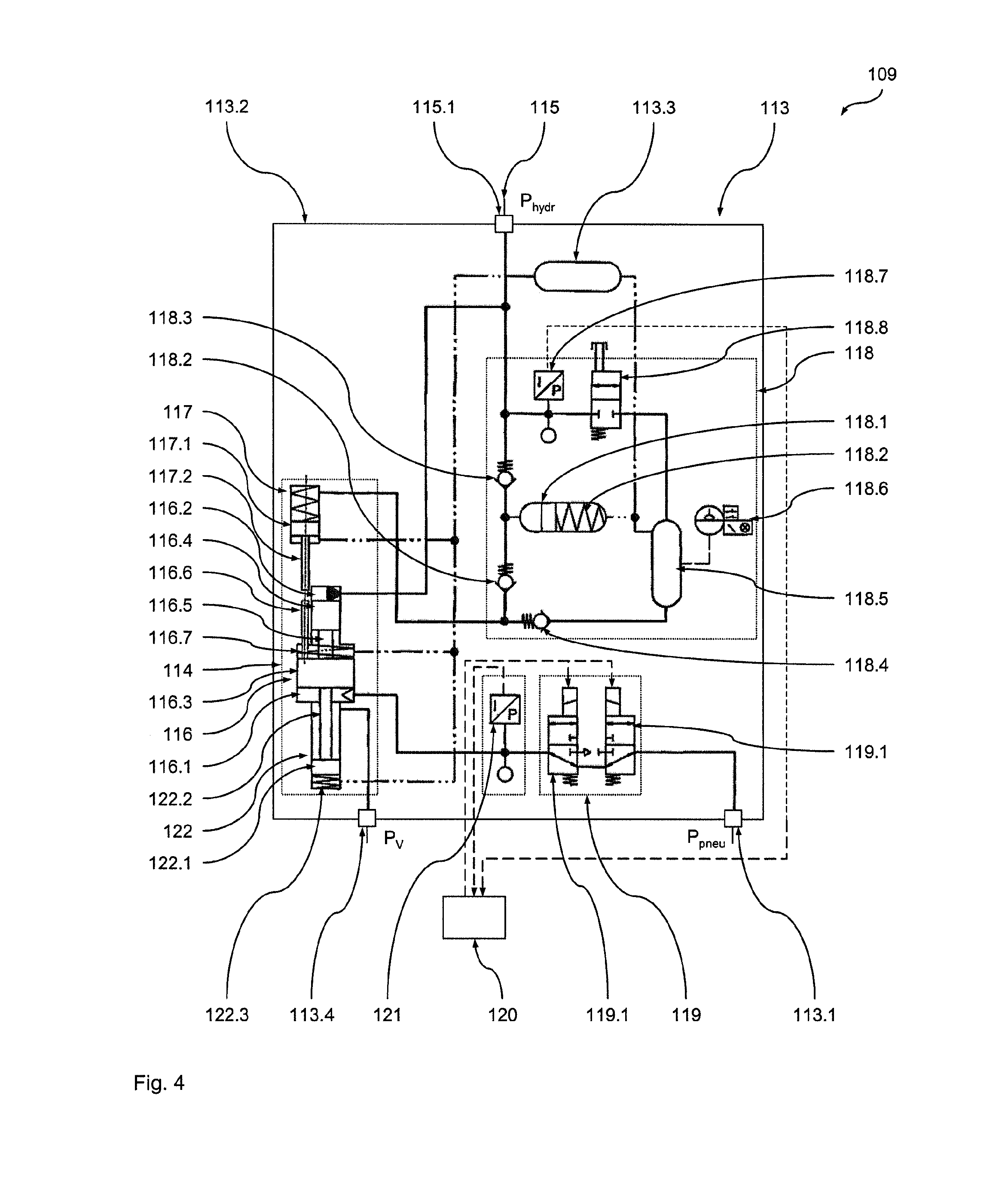
The invention is a braking system for vehicles that can be seamlessly integrated into existing pneumatic braListener's archetype without having to modify any of their security-related areas. This makes it ideal for retrofitting existing vehicles with pneumatic brakes. The hydraulic part of the braking system can be seen as a simplified version of a traditional braking system, making the approval process easier. The design includes a converting device that converts pneumactic into hydraulic braking energy. This process can be done in a compact and replaceable manner. The converting device operates on a displacement principle using a piston-cylinder arrangement or other similar systems. The output pressure is higher than the input pressure, with a pressure conversion ratio of 10-300 times. This allows for compact braking apparatuses with high power density.

Problems solved by technology

Such braking systems, due to the pneumatic operating principle, require a relatively large amount of space within the running gear or within the wagon body of the vehicle.
Especially in a running gear of a modern railway vehicle (not least due to the ever increasing complexity of such running gears, especially the steady increase in the number of active components of such running gears) this leads to increasing problems in the integration of the braking equipment.
Another problem arises from the frequent requirement for the lowest possible weight of the vehicle, which is not least motivated by the significant savings that can arise for the operator in the operation of the vehicle.
Furthermore, the known braking apparatuses include a wear adjustment mechanics, which are built-in to the brake mechanics, which are mostly relatively complicated and malfunction-prone and which are intended to compensate for wear of the friction elements and, thus, to provide an almost equally short stroke of the brake actuator over the life of the friction elements.
All this leads to a considerable mass of the braking apparatus.

Method used


Image

  • Brake System for a Vehicle
  • Brake System for a Vehicle
  • Brake System for a Vehicle

Examples


first embodiment

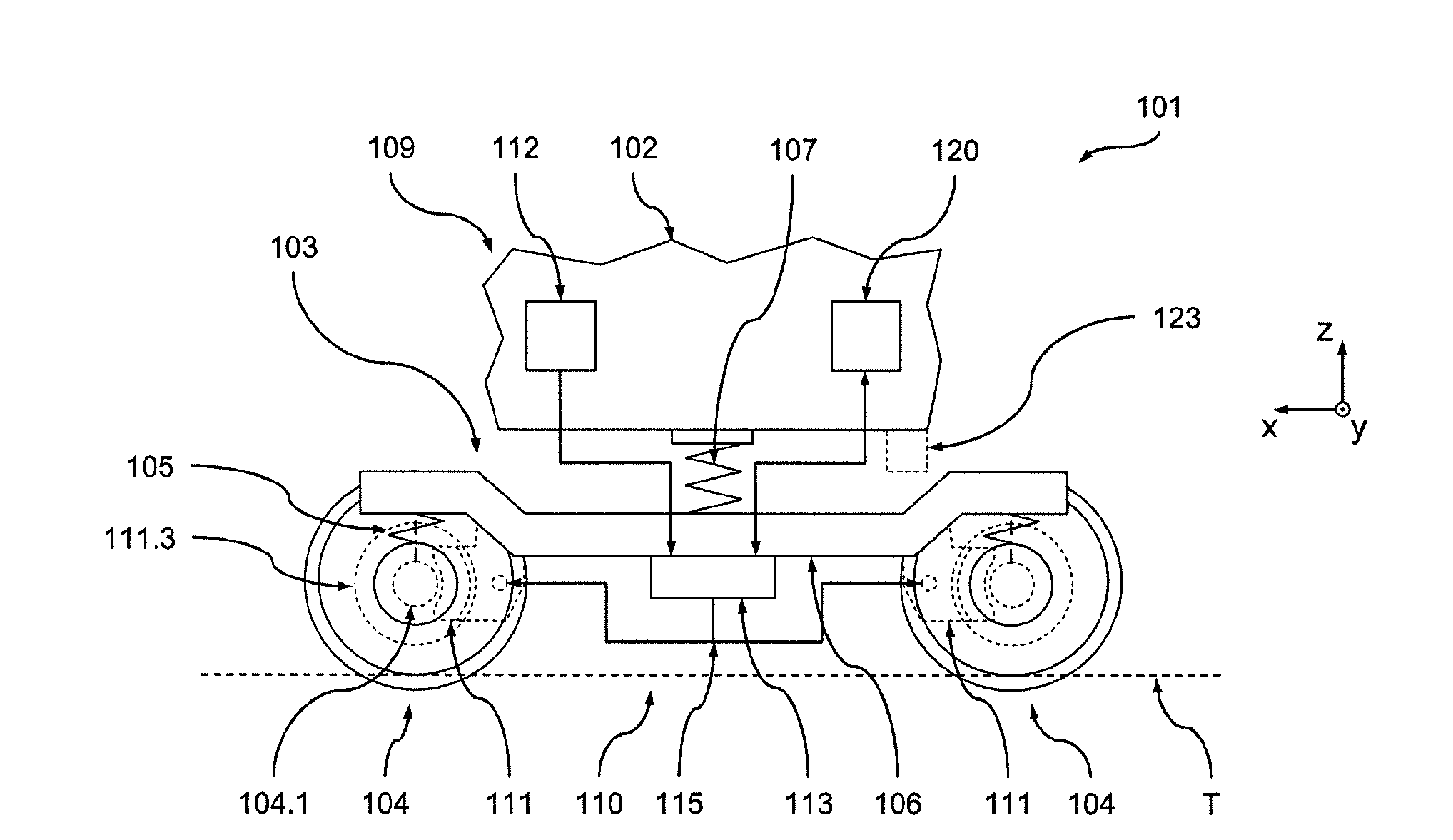
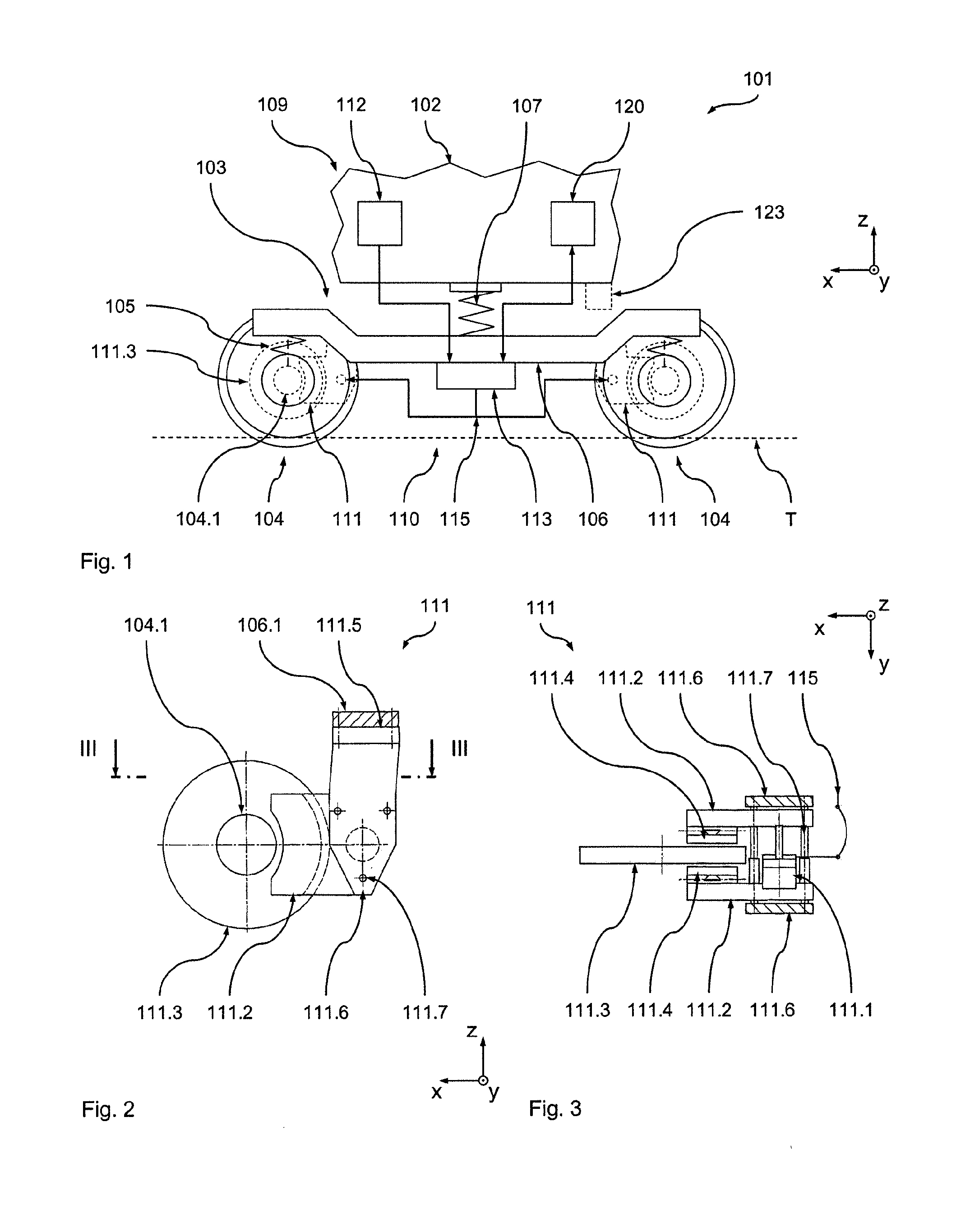
[0052]In the following, with reference to FIGS. 1 to 4 a first preferred embodiment of the vehicle according to the invention in the form of a rail vehicle 101 will be described.

[0053]The vehicle 101 comprises a wagon body 102 which is supported in the region of its two ends respectively on a running gear in the form of a bogie 103. It is understood, however, that the present invention can also be used in conjunction with other configurations in which the wagon body is supported only on one running gear.

[0054]For easier understanding of the following explanations, a vehicle coordinate system x, y, z (defined by the wheel contact plane of the bogie 103 on the rails T) is introduced in the figures, wherein the x-coordinate designates the longitudinal direction of the rail vehicle 101, the y-coordinate designates the transverse direction of the rail vehicle 101, and the z-coordinate designates the height direction of the rail vehicle 101, respectively.

[0055]The bogie 103 comprises two ...

second embodiment

[0092]In the following, a further preferred embodiment of the braking system 209 according to the invention is described with reference to FIGS. 5 and 6, which can replace the braking system 109 in the vehicle 101. The braking system 209 in its structure and functionality basically corresponds to the braking system 109, such that only the differences shall be discussed here. Similar components are thus given reference numerals elevated by the value 100. Unless deviating statements are made in the following, reference is made to the above statements concerning the characteristics and functions of these components.

[0093]The only difference of the braking system 209 to the brake system 109 lies in the design of the braking apparatus 211, which is designed as a so-called suspended shackle brake in the present example. The latter has suspended shackles 211.6 articulated to an adaptor device 211.5 of the interface flange 106.1. The suspended shackles 211.6 in turn carry the calipers 211.2...


PUM


Abstract

A brake system for a vehicle, in particular a rail vehicle, has a braking device, wherein the braking device has a braking apparatus for braking at least one wheel of the vehicle and the braking device has a pneumatic connecting apparatus for connecting to a pneumatic energy supply unit for supplying the braking apparatus with pneumatic braking energy. The braking apparatus is designed as a hydraulic braking apparatus, wherein the braking device has a conversion apparatus connected between the pneumatic connecting apparatus and the braking apparatus for converting the pneumatic braking energy into hydraulic braking energy.

Description

BACKGROUND OF THE INVENTION[0001]The present invention relates to a braking system for a vehicle, in particular a rail vehicle, with a braking device, wherein the braking device has a braking apparatus for braking at least one wheel of the vehicle and the braking device has a pneumatic connection device for connection to a pneumatic energy supply unit for supplying the braking apparatus with pneumatic braking energy. The present invention further relates to a running gear for a vehicle and a vehicle having a braking system according to the invention. Likewise, it relates to a method for actuating a braking apparatus of a vehicle.[0002]In modern rail vehicles, such as locomotives, multiple traction units, passenger coaches and, increasingly, freight wagons (but also in other vehicles) such pneumatic braking systems are known, in which, usually, disc brake devices (hence, typically, at least one brake disc and brake actuator together with associated brake mechanics) are used. As a rul...

Claims


Application Information

Patent Timeline
Patent Type & Authority Applications(United States)
IPC IPC(8): B60T13/44B61H11/00B60T8/40B61H5/00
CPCB60T13/44B60T8/4077B61H11/00B61H5/00B60T13/365B60T13/583B60T13/665B60T17/228F16D55/2245
Inventor POSTLER, CLAUS-DIETER
Owner BOMBARDIER TRANSPORTATION GMBH
Learn More