Heat exchanger plate and plate heat exchanger comprising such a heat exchanger plate

a technology of heat exchanger plate and heat exchanger plate, which is applied in the direction of indirect heat exchanger, laminated elements, light and heating apparatus, etc., can solve the problems of increasing the diameter of the port holes in the heat exchange plate, increasing the cost of equipment for proper operation of the phe, and increasing the heat exchange capacity of the heat exchange plate. , to achieve the effect of facilitating the manufacture of the heat exchanger plate and minimizing the effect of the heat transfer capability of the heat exchang

Active Publication Date: 2015-09-03
ALFA LAVAL CORP AB
View PDF10 Cites 20 Cited by
  • Summary
  • Abstract
  • Description
  • Claims
  • Application Information

AI Technical Summary

Benefits of technology

[0017]The port hole of the heat exchanger plate may be such that a first curved line of the curved lines, which connects the first and second corner points, and a third curved line of the curved lines, which connects the third and first corner points, are similar but mirror inverted in relation to each other. Such uniform curved lines enable a symmetric port hole where the symmetry axis is parallel to the first imaginary straight line. As mentioned above, a symmetric port hole may facilitate manufacturing of the heat exchanger plate.
[0018]Finally, the upper half of the heat exchanger plate may comprise a second area provided with a second corrugation pattern and a third area provided with a third corrugation pattern. The second and third areas are arranged...

Problems solved by technology

The smaller the inlet and outlet ports are, the larger the pressure drop of the fluids inside the PHE gets and the more powerful, and thus expensive, equipment is required for proper operation of the PHE.
However, enlarging the diameter of the inlet and outlet ports means increasing the diameter of the of the port holes in the heat transfe...

Method used


Image

  • Heat exchanger plate and plate heat exchanger comprising such a heat exchanger plate
  • Heat exchanger plate and plate heat exchanger comprising such a heat exchanger plate
  • Heat exchanger plate and plate heat exchanger comprising such a heat exchanger plate

Examples


Embodiment Construction

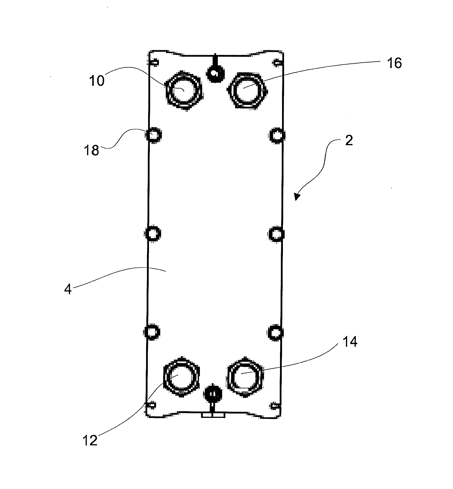
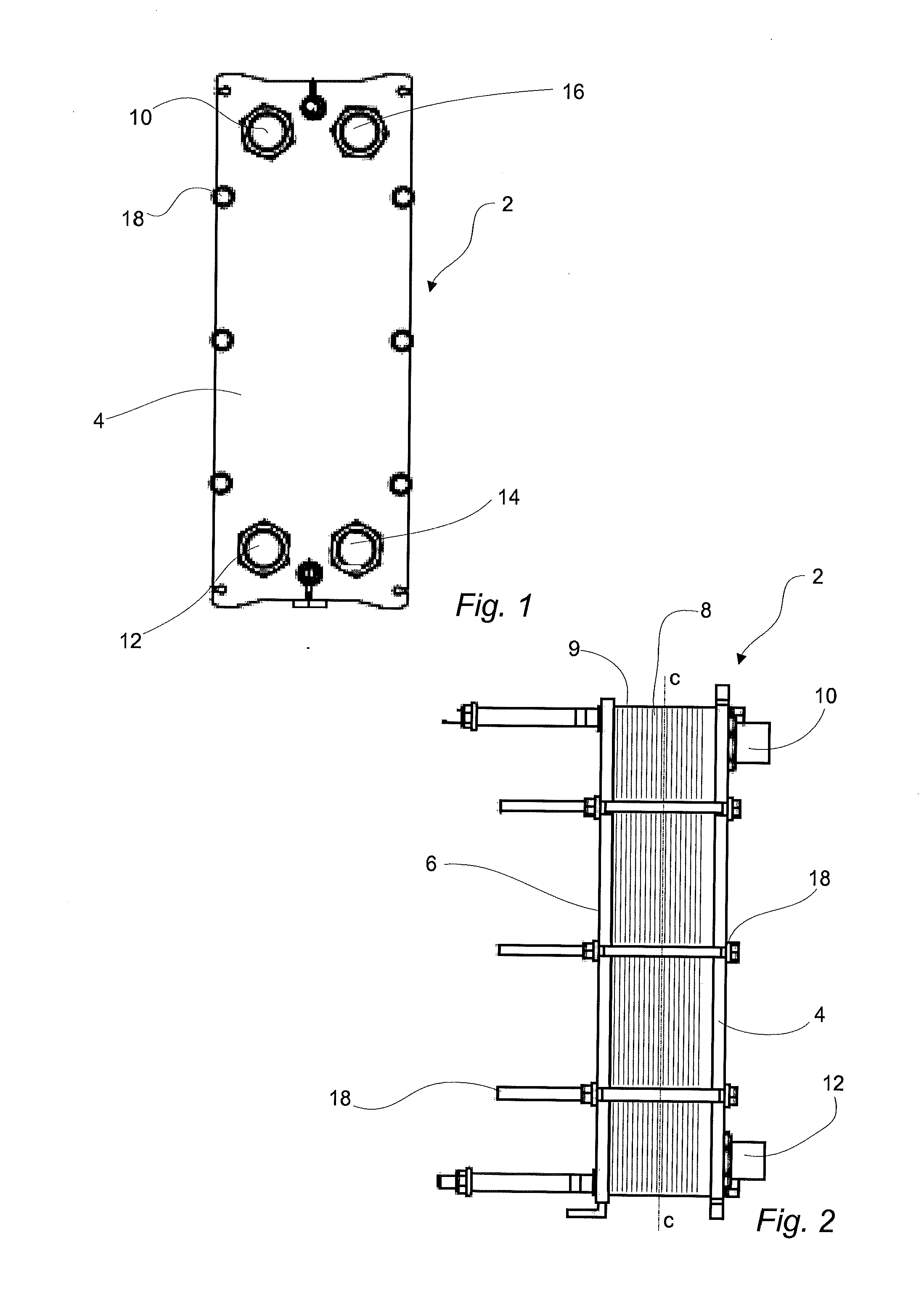
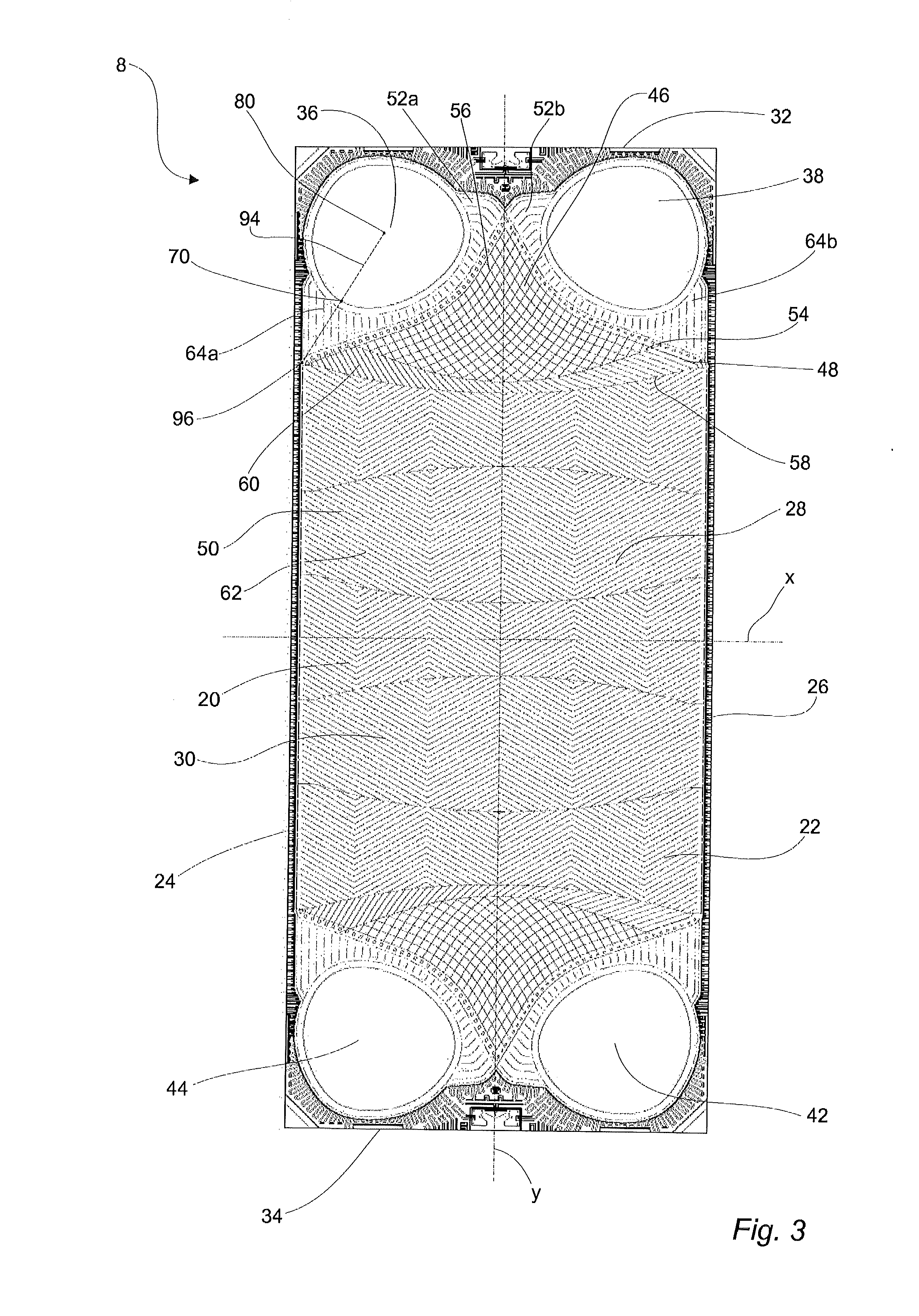
[0026]With reference to FIGS. 1 and 2, a gasketed plate heat exchanger 2 is shown. It comprises heat exchanger plates in the form of a first end plate 4, a second end plate 6 and a number of heat transfer plates arranged between the first and second end plates 4 and 6, respectively. The heat transfer plates are of two different types. However, the heat transfer plate parts that the present invention is related to is similar on all heat transfer plates. Therefore, the difference between the two heat transfer plate types will not be discussed further herein. One of the heat transfer plates, denoted 8, is illustrated in further detail in FIG. 3. The different types of heat transfer plates are alternately arranged in a plate pack 9 with a front side (illustrated in FIG. 3) of one heat transfer plate facing the back side of a neighboring heat transfer plate. Every second heat transfer plate is rotated 180 degrees, in relation to a reference orientation (illustrated in FIG. 3), around a n...


PUM


Abstract

A heat exchanger plate has a vertical center axis dividing the plate into a left and a right half delimited by a first and second long side, respectively. A horizontal center axis divides the plate into an upper and a lower half delimited by a first and second short side, respectively. The plate includes a port hole with a reference point that coincides with a center point of a biggest imaginary circle that can be fitted into the port hole. The port hole is arranged within the left half and the upper half. The porthole has a form defined by a number of corner points of an imaginary plane geometric figure of which at least one is displaced from an arc of the circle, and the same number of thoroughly curved lines connecting the corner points. The corner points include first, second and third corner points.

Description

TECHNICAL FIELD[0001]The invention relates to a heat exchanger plate according to the preamble of claim 1. The invention also relates to a plate heat exchanger comprising such a heat exchanger plate.BACKGROUND ART[0002]Plate heat exchangers typically consist of two end plates in between which a number of heat transfer plates are arranged in an aligned manner. In one type of well-known PHEs, the so called gasketed plate heat exchangers, gaskets are arranged between the heat transfer plates. The end plates, and therefore the heat transfer plates, are pressed towards each other whereby the gaskets seal between the heat transfer plates. The gaskets define parallel flow channels between the heat transfer plates through which channels two fluids of initially different temperatures alternately can flow for transferring heat from one fluid to the other.[0003]The fluids enter and exit the channels through inlet and outlet ports, respectively, which extend through the plate heat exchanger and...

Claims


Application Information

Patent Timeline
IPC IPC(8): F28F3/08
CPCF28F3/08F28F3/046F28F3/083F28F3/086F28D9/005F28D9/0043
Inventor NILSSON, JOHANHEDBERG, MAGNUS
Owner ALFA LAVAL CORP AB
Why Eureka
Try Eureka