Polarization splitting multiplexing device, optical system, and display unit
a multiplexing device and polarization technology, applied in multiplex communication, instruments, optical elements, etc., can solve the problems of affecting affecting the quality of picture, etc., and achieve the effect of improving the accuracy of mutual inclination, simple configuration, and achieving desired optical delay
- Summary
- Abstract
- Description
- Claims
- Application Information
AI Technical Summary
Benefits of technology
Problems solved by technology
Method used
Image
Examples
first embodiment
[0052]Hereinafter, a first embodiment of the disclosure will be described in detail with reference to drawings.
[0053](Display Unit)
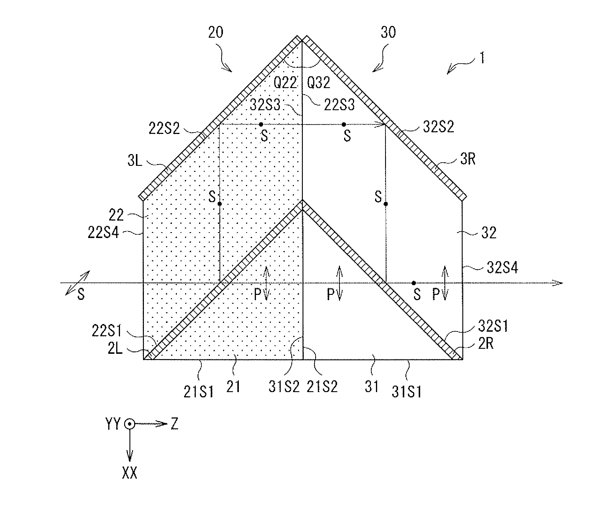
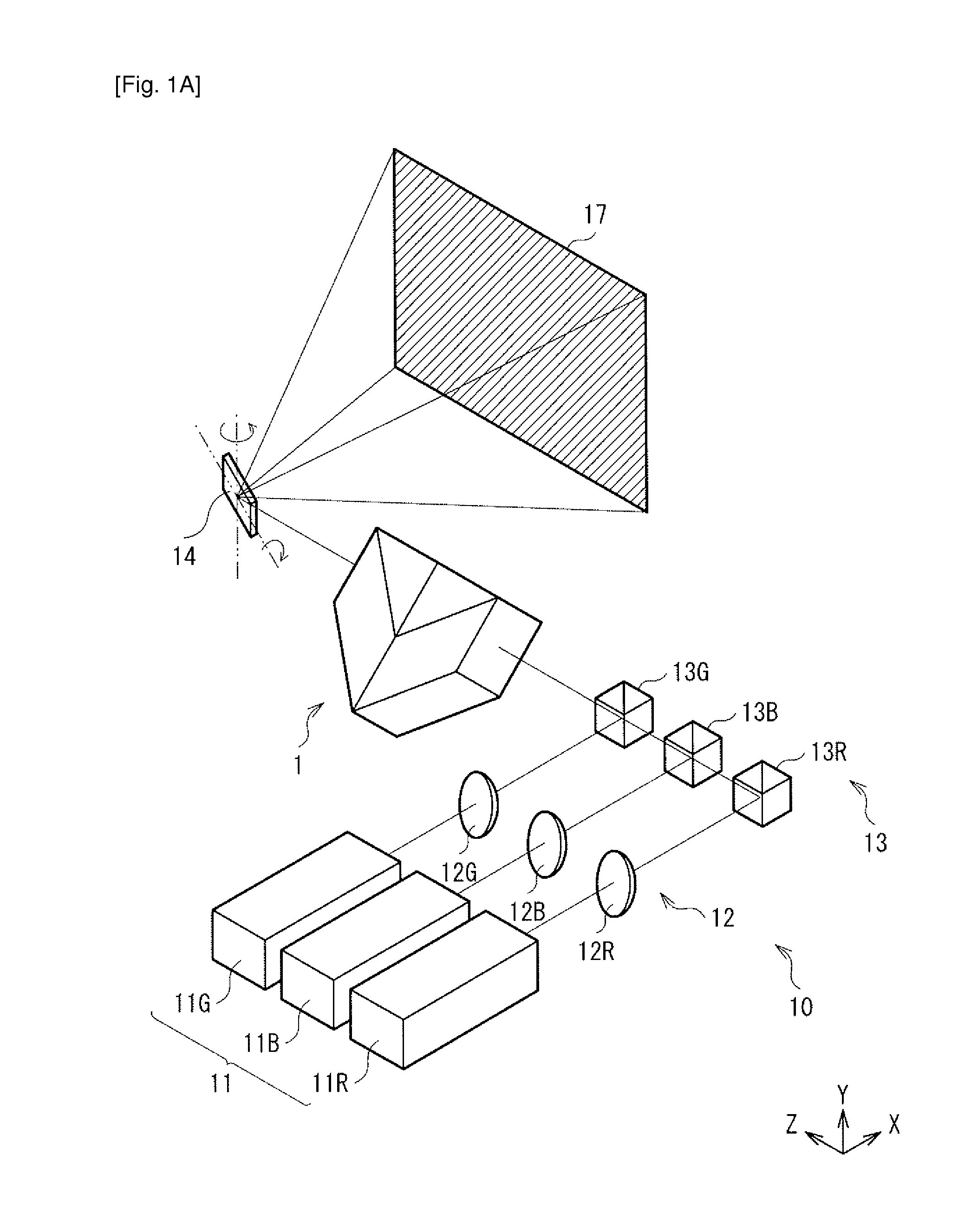
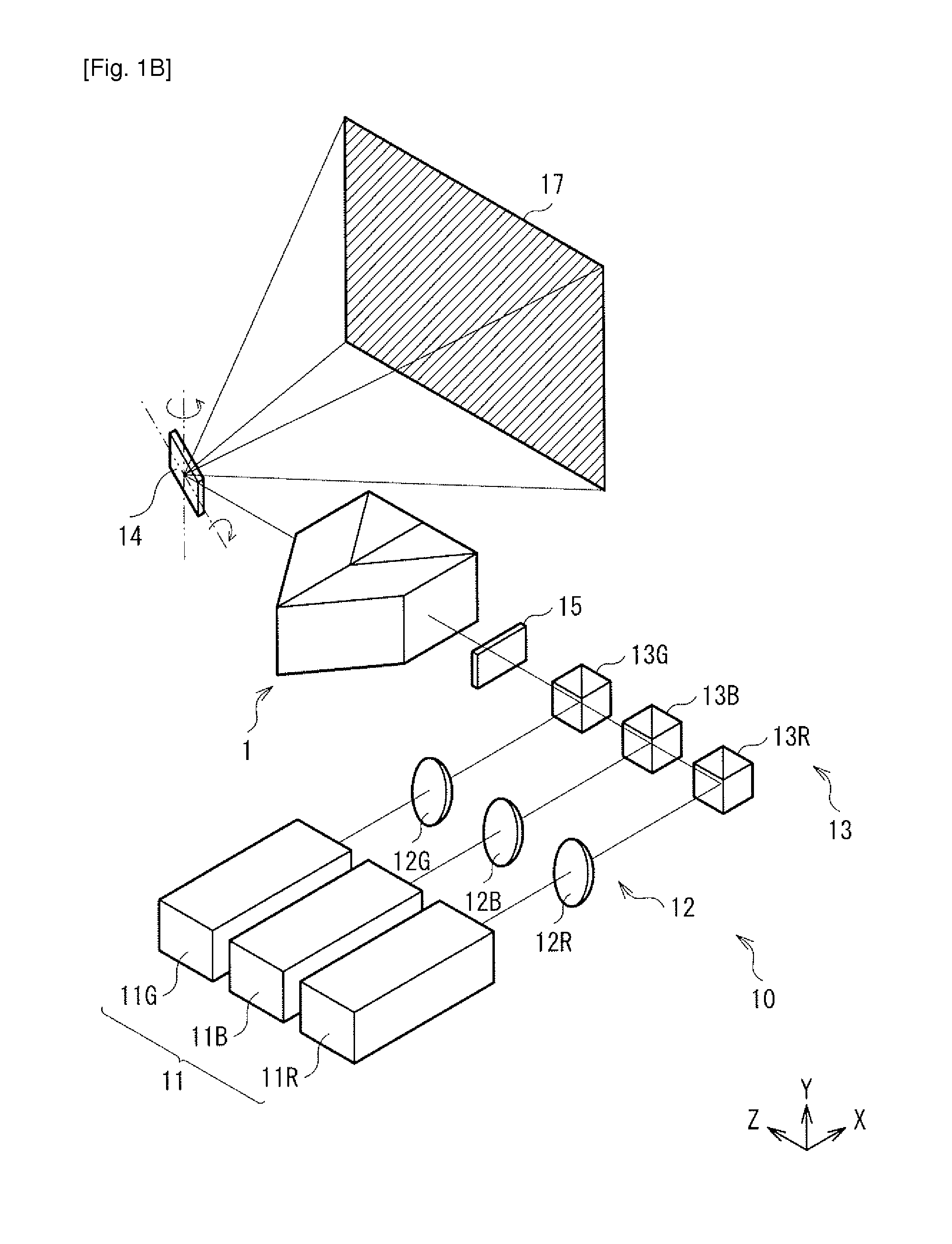
[0054]FIG. 1A illustrates a display unit of the first embodiment. For example, the display unit may be a laser beam scanning projector using a semiconductor laser as a light source. As illustrated in FIG. 1A, the display unit includes a light source section 10, a polarization splitting multiplexing device 1 allowing a laser beam from the light source section 10 to pass therethrough, and a micro electro mechanical system (MEMS) mirror 14 as a scanning section. Further, as illustrated in FIG. 1B, the display unit may include a quarter-wavelength plate 15 on an optical path between the polarization splitting multiplexing device 1 and the light source section 10.
[0055](Optical System)
[0056]FIG. 2A illustrates an optical system in the display unit illustrated in FIG. 1A. For example, the optical system may include the light source section 10 and the polarizat...
second embodiment
[0100]A second embodiment of the disclosure will be described in detail below with reference to drawings.
[0101]FIG. 6A illustrates a detailed configuration example of a polarization splitting multiplexing device 1A as the second embodiment. The polarization splitting multiplexing device 1A is applied to the display unit of the above-described first embodiment. However, unlike the polarization splitting multiplexing device 1, in the polarization splitting multiplexing device 1A, it is not necessary to incline a polarization direction of an incident laser beam of linear polarization, with respect to a surface including an optical path of the laser beam that passes through the polarization splitting multiplexing device 1A. In other words, it is sufficient to set the angle Q to 0 degree or 180 degrees. In addition, a right-handed circularly polarized light beam or a left-handed circularly polarized light beam may enter the polarization splitting multiplexing device 1A, in place of the l...
experimental example 1
Experimental Example 1-1
[0152]In the present Experimental Example, a display unit having an optical system (FIG. 14A) that includes the polarization splitting multiplexing device 1 of the above-described embodiment was fabricated, and the reducing effect of speckle was evaluated. Incidentally, the distance between the optical element 20 and the optical element 30 was variable, and the optical delay distance D was variable. Note that, in FIG. 14A, illustration of the color multiplexing section 13 is omitted. In addition, in the optical system, in a plane orthogonal to an optical axis, the polarization splitting multiplexing device 1 was inclined by 45 degrees with respect to the light source section 10 with the optical axis serving as a central axis, as illustrated in FIG. 14B. In other words, a surface including the optical path of the laser beam in the polarization splitting multiplexing device 1 was arranged so as to make an angle of 45 degrees or 135 degrees with respect to a pol...
PUM
 Abstract
Description
Claims
Application Information
 - R&D
- Intellectual Property
- Life Sciences
- Materials
- Tech Scout
- Unparalleled Data Quality
- Higher Quality Content
- 60% Fewer Hallucinations
Browse by: Latest US Patents, China's latest patents, Technical Efficacy Thesaurus, Application Domain, Technology Topic, Popular Technical Reports.
© 2025 PatSnap. All rights reserved.Legal|Privacy policy|Modern Slavery Act Transparency Statement|Sitemap|About US| Contact US: help@patsnap.com


