Shoe Sole Focusing on Windlass Mechanism

a technology of windlass and shoe sole, which is applied in the field of shoe sole can solve the problems of limited foot movement, flatfoot and hallux valgus, and conventional techniques that are not focusing on the windlass mechanism and using this mechanism, so as to facilitate the upward displacement of the area, facilitate the arch of the foot, and facilitate the effect of shoe sole flex

Inactive Publication Date: 2015-09-10
ASICS CORP
View PDF11 Cites 26 Cited by
  • Summary
  • Abstract
  • Description
  • Claims
  • Application Information

AI Technical Summary

Benefits of technology

[0025]According to the present invention, the presence of the second transverse groove and the third transverse groove allows for a portion of the shoe sole from the middle foot portion to the rear foot portion to deform (flex) into an upwardly protruding shape. Therefore, when the toe is elevated facing upward and the MP joint is extended over the first transverse groove, the plantar muscles, including at least the plantar aponeurosis, are rolled up upward, thereby tensioning the plantar aponeurosis, which makes it easier for the arch of the foot to rise.
[0026]Particularly, the second transverse groove, provided in an area between the Chopart's joint and the Lisfranc joint, including the navicular bone where the arch of the foot is highest, is deeper than the first transverse groove, and is equal to or deeper than the third transverse groove. Therefore, the rest of the midsole is thin and it becomes easier for the shoe sole to flex, thereby facilitating the upward displacement of the area where the arch is highest.
[0027]That is, if no reinforcement device is provide

Problems solved by technology

However, these conventional techniques are probably not focusing on the windlass mechanism and using this mechanism.
On the other hand, lowering of the arch may lead to flatfoot and hallu

Method used


Image

  • Shoe Sole Focusing on Windlass Mechanism
  • Shoe Sole Focusing on Windlass Mechanism
  • Shoe Sole Focusing on Windlass Mechanism

Examples


embodiment 1

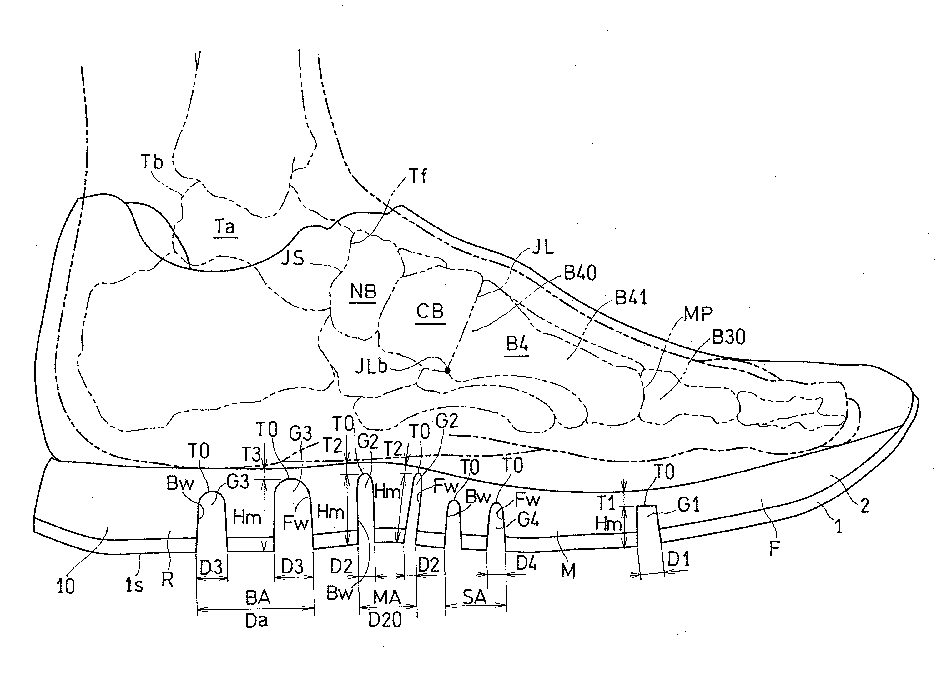
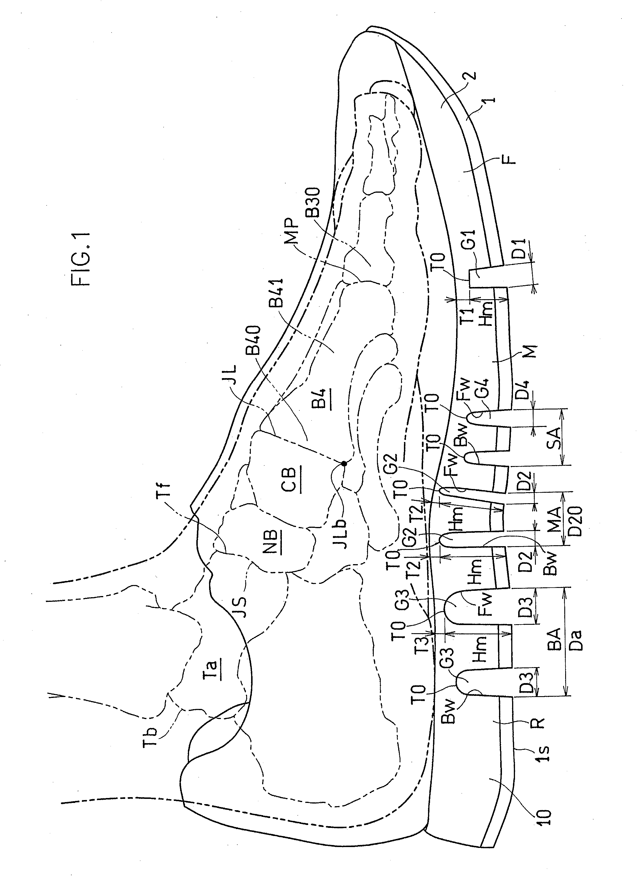
[0095]FIGS. 1 to 4 show Note that in order to facilitate the description of the invention, FIG. 1 shows the medial side of a shoe for the left foot whereas FIG. 2 shows a lateral side view of a shoe for the right foot.

[0096]As shown in FIGS. 1 and 2, a shoe sole includes an outsole 1, and a midsole 2. In various figures, minute grooves (so-called a design) formed on a tread surface 1S of the outsole 1 are omitted.

[0097]In the present embodiment, the outsole 1 and the midsole 2 are placed across the fore foot portion F, the middle foot portion M and the rear foot portion R. The outsole 1 is formed by a foamed or non-foamed rubber, for example, and has the tread surface 1s which has a higher abrasion resistance than the midsole 2 and which is to be in contact with the road surface.

[0098]The midsole 2 is formed by a foamed resin such as EVA, for example, and is placed on the outsole 1, as shown in FIG. 2, for reducing the impact of landing. Therefore, the midsole 2 is formed thicker t...

embodiment 2

[0134]As shown in Embodiment 2 of FIG. 5, some or all of the second to fourth transverse grooves G2 to G4 may be set to a length such that they extend from the medial edge 10 toward the lateral edge 11 past the longitudinal axis A1 but do not reach the lateral edge 11. The arch of the foot is high on the medial side, and the effect of the windlass mechanism can be therefore expected as long as the medial side portion of the sole can flex sufficiently.

[0135]Preferably, the transverse grooves G1 to G4 can extend over about ⅔ the total width from the medial edge 10 to the lateral edge 11 in the area where the transverse grooves G1 to G4 are provided.

[0136]Note that as opposed to the example shown in FIG. 5, the second and third transverse grooves G2 and G3 may be provided across the total width, whereas the first and fourth transverse grooves G1 and G4 are provided so as to extend from the medial edge 10 past the longitudinal axis A1 and into a part of the lateral side portion.

[0137]As...

embodiment 3

[0138]In Embodiment 3 of FIG. 6, there may be a single, i.e., only one, second transverse groove G2 that is deeper than the third transverse groove G3. In this example, the depth of a second transverse groove G2 that is immediately anterior to the posterior second transverse groove G2 is smaller than the depth of one of the third transverse grooves G3.

[0139]Where there is one second transverse groove G2 that is deeper than the third transverse groove G3, as in this example, at least the ceiling TO of the second transverse groove G2 is preferably placed directly below the navicular bone NB. This is because the navicular bone NB is located at the apex of the arch of the foot.


PUM


Abstract

The second transverse groove, provided in an area between the Chopart's joint and the Lisfranc joint, including the navicular bone where the arch of the foot is highest, is deeper than the first transverse groove, and is equal to or deeper than the third transverse groove. Therefore, the rest of the midsole is thin and it becomes easier for the shoe sole to flex, thereby facilitating the upward displacement of the area where the arch is highest. Thus, it is possible to suppress the lowering of the arch even if an exercise is continued over a long time. On the other hand, a flexion area including at least one third transverse groove is provided directly below the talus, and has a larger width than other transverse grooves. This makes it easier for the rear foot portion directly below the talus to flex, thereby facilitating the upward displacement of the area of the arch.

Description

TECHNICAL FIELD[0001]The present invention relates to a shoe sole focusing on the windlass mechanism.BACKGROUND ART[0002]Shoes with multiple or many transverse grooves extending in the transverse direction on the bottom surface of the shoe sole are well known in the art.CITATION LISTPatent Literature[0003]First Patent Document: U.S. Pat. No. 7,168,190 B1 (front page)[0004]Second Patent Document: US2011-016746 A1 (front page)[0005]Third Patent Document: US2011-232130 A1 (front page)[0006]Fourth Patent Document: PCT / US2004 / 033111 (abstract)[0007]Fifth Patent Document: JP07-289306 A (abstract)SUMMARY OF INVENTION[0008]However, these conventional techniques are probably not focusing on the windlass mechanism and using this mechanism.[0009]Now, it is known that when the MP joint is hyperextended, the plantar aponeurosis is tensioned to thereby pull the calcaneal bone forward, thus increasing the arch height, and this series of actions is called the “windlass mechanism”.[0010]It is known ...

Claims


Application Information

Patent Timeline
IPC IPC(8): A43B13/14A43B7/18
CPCA43B7/18A43B13/141A43B13/122A43B13/125A43B13/16
Inventor BESSHO, AYUMORIYASU, KENTANISHIWAKI, TSUYOSHIFUJITA, HISANORI
Owner ASICS CORP
Why Eureka
Try Eureka