Dental irradiation device and system

Active Publication Date: 2015-09-10
3M INNOVATIVE PROPERTIES CO
View PDF26 Cites 34 Cited by
  • Summary
  • Abstract
  • Description
  • Claims
  • Application Information

AI Technical Summary

Benefits of technology

[0039]In one embodiment the dental irradiation device is adapted to display an image captured by the image sensing unit superimposed with a crosshair having a position and an area size indicator. The area size indicator is adapted to indicate an area in which the emitted light is suitable to harden a dental mate

Problems solved by technology

Additionally, a pivotal connection between the housing and the handle permits limited pivotal adjus

Method used


Image

  • Dental irradiation device and system
  • Dental irradiation device and system
  • Dental irradiation device and system

Examples


Embodiment Construction

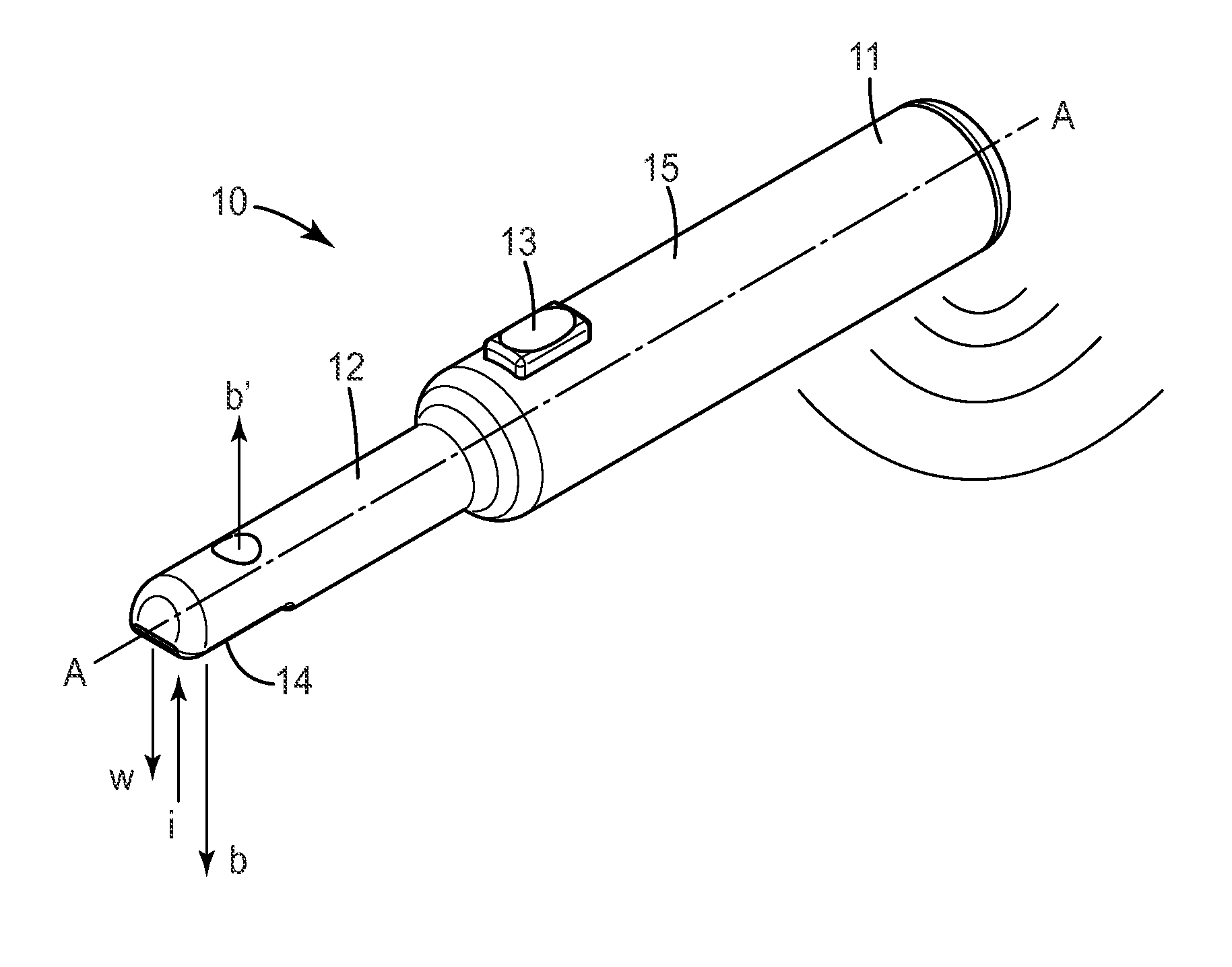
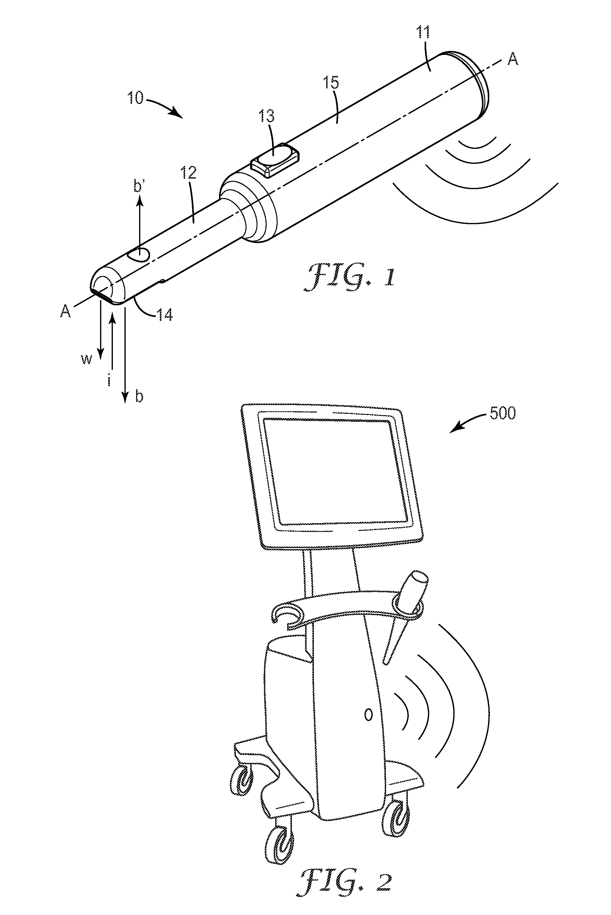
[0071]FIG. 1 shows a dental irradiation device 10 comprising a body 11 and an intra-oral tip 12. The device 10 extends along a longitudinal axis A which in the example is generally straight, but may in another example be curved. The intra-oral tip 12 laterally to the longitudinal axis A has a reduced dimension relative to the body 11. This minimizes the space which is needed for positioning the intra-oral tip 12 in a patient's mouth, whereas the body 11 allows for accommodation of electronic components for operation of the device 10. The body 11 forms a handle 15 allowing a user to hold the device 10, for example during operation. The device 10 is generally adapted for emitting overall blue light and preferably for emitting white light. The device may be adapted for emitting blue light and simultaneously or alternatively white light. Further the device 10 is adapted for image capturing. Although not visible in detail in this Figure the device 10 has a first light emitting unit for e...


PUM


Abstract

A dental irradiation device comprises a first light emitting unit for emitting blue light adapted for light hardening of a dental material. The device further comprises a second light emitting unit and an image sensing unit which are adapted for cooperation with each other for simultaneous illumination and image capturing. The device facilitates hardening of dental materials and provides, inter alia, additional diagnostic functions.

Description

FIELD OF THE INVENTION[0001]The invention relates to a dental irradiation device which is adapted for emitting blue light for light hardening of a dental material as well as for image capturing including lighting for the image capturing. Further the invention relates to a system comprising such a device and a computer connectable with the device.BACKGROUND ART[0002]Light hardenable or light curable materials are widely used in dentistry for the restoration of teeth. Many of such materials are made to provide optical characteristics that resemble those of natural teeth. Further such materials typically can be placed precisely and conveniently, can be hardened instantly, and the hardened material is typically relatively durable. Accordingly these materials are favored alternatives to less pleasant looking and over time self-hardening materials, like for example amalgam.[0003]Light hardenable materials often include a polymerizable matrix material and filler materials including coloran...

Claims


Application Information

Patent Timeline
IPC IPC(8): A61C13/15A61B1/05A61B1/06A61B1/24
CPCA61C19/004A61B1/06A61B1/05A61B1/24A61B1/0676A61B1/247A61B1/0653A61B1/0684F04C2270/041A61B1/00105A61B1/00124A61B1/0655
Inventor GRAMANN, JENSWELKER, STEFANMUELLER, THOMAS K.SCHEPKE-GERLACH, KORBINIANKELZ, RALFWATZEK, KARINHARRE, MANFREDSCHMID, RUDOLF
Owner 3M INNOVATIVE PROPERTIES CO
Why Eureka
Try Eureka