
Pneumatic vehicle tire

a technology for pneumatic vehicles and tires, applied in the direction of tyre tread bands/patterns, heavy duty tyres, non-skid devices, etc., can solve the problems of less satisfactory traction characteristics and handling characteristics of known vehicle tires, and achieve stable treads, good traction, and improved handling characteristics

Active Publication Date: 2015-09-10
CONTINENTAL REIFEN DEUTSCHLAND GMBH
View PDF7 Cites 38 Cited by
  • Summary
  • Abstract
  • Description
  • Claims
  • Application Information

AI Technical Summary

Benefits of technology

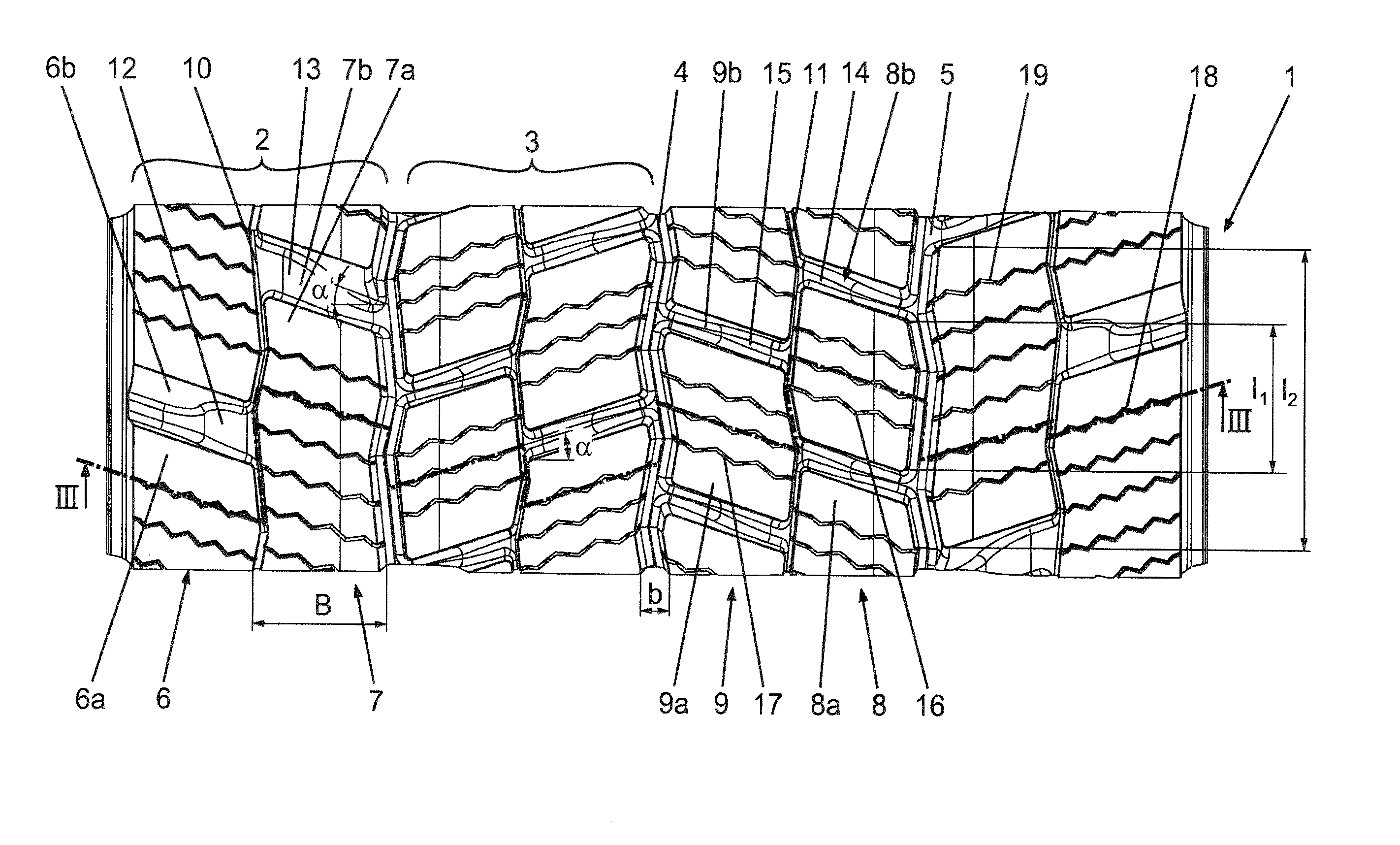
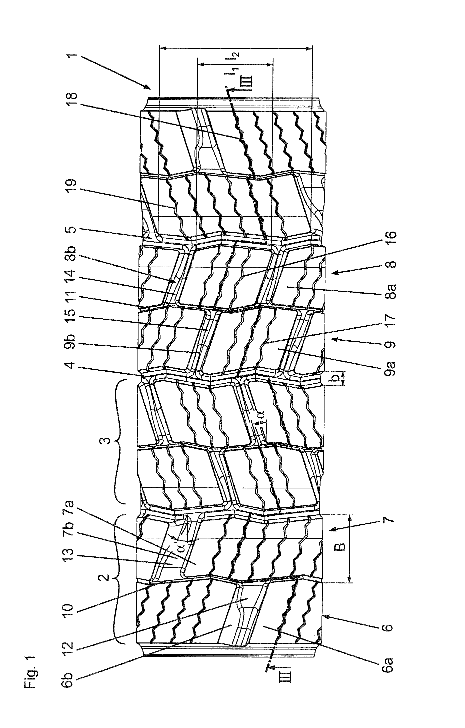
The patent is about a special tire design for snow, which improves its grip on the snow-covered surface. The design features a depth profile with transverse grooves and narrow circumferential grooves between the blocks in the tire. These transverse grooves and sipes help to provide good traction. The width of the transverse grooves in the shoulder-side block row pairs should be wider than the ones in the middle block row pairs. Additionally, the depth of the circunferential grooves between the blocks in the shoulder-side block row pairs should not exceed35% of the maximum profile depth, while those in the middle block row pairs should not exceed55% of the maximum profile depth. This design also allows for higher stability in the shoulder-side blocks, which in turn improves handling characteristics.

Problems solved by technology

On roadways with a relatively thick layer of snow or on steep snow-covered roadways, however, the traction characteristics and handling characteristics of the known vehicle tire are less satisfactory.

Method used


Image

  • Pneumatic vehicle tire
  • Pneumatic vehicle tire
  • Pneumatic vehicle tire

Examples


Embodiment Construction

[0016]The invention is concerned with a specific embodiment of a tread of utility vehicle tires, preferably bus tires, which is particularly suitable for use under winter driving conditions, in particular on snow-covered or icy ground.

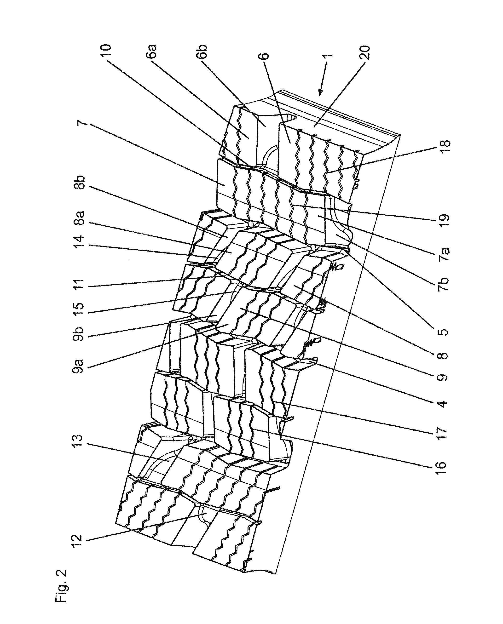
[0017]FIG. 1 shows a plan view of a circumferential section of an embodiment according to the invention of a tread 1, having in each case two block row pairs (2, 3) in each tread half. Along the equatorial plane of the pneumatic vehicle tire, there extends around the tread 1 a central circumferential groove 4 which, in the embodiment shown, has a slightly zigzag-shaped or undulating profile with a small amplitude. The shoulder-side block row pairs 2 are separated from the middle block row pairs 3 by a circumferential groove 5 which likewise runs in zigzag-shaped or undulating fashion with a small zigzag or undulation amplitude. The circumferential grooves 4 and 5 have, at the tread surface, a constant width (b) of 6 mm to 10 mm, have a substantially U-...


PUM


Abstract

A vehicle tire has outer shoulders and two tread halves. The vehicle tire includes a tire tread having six block rows and a plurality of circumferential grooves. Mutually adjacent ones of the block rows are separated from each other by a corresponding one of the plurality of circumferential grooves. Each of the block rows has a plurality of individual blocks and the individual blocks of each of the block rows are separated from each other by mutually parallel essentially straight transverse grooves running at an angle to the axial direction of the tire. The circumferential grooves includes first circumferential grooves having a maximum profile depth and second circumferential grooves. The block rows are arranged such that each tread profile half has two pairs of block rows. The pairs of block rows of each tread profile half are separated from each other by a corresponding one of the first circumferential grooves. The block rows of each of the pairs of block rows are separated from each other by a corresponding one of the second circumferential grooves. The second circumferential grooves have a second profile depth less than the maximum profile depth. A first portion of the transverse grooves defines first outlet locations to the first circumferential grooves and a second portion of the transverse grooves has first outlet locations to the outer shoulders. The transverse grooves have a depth approximately corresponding to the maximum profile depth at the first outlet locations. The transverse grooves define second outlet locations to a corresponding one of the second circumferential grooves. The transverse grooves have a depth corresponding to the second profile depth at the second outlet locations.

Description

CROSS REFERENCE TO RELATED APPLICATIONS[0001]This application is a continuation application of international patent application PCT / EP2013 / 068044, filed Sep. 2, 2013, designating the United States and claiming priority from German application 10 2012 111 116.2, filed Nov. 19, 2012, and the entire content of both applications is incorporated herein by reference.FIELD OF THE INVENTION[0002]The invention relates to a pneumatic vehicle tire for a utility vehicle tire, in particular for use under winter driving conditions, having a tread with at least six block rows which run in encircling fashion in a circumferential direction and which are of substantially corresponding width and which are separated from one another by circumferential grooves which run in encircling fashion in the circumferential direction, wherein the blocks of the individual block rows are separated from one another by at least substantially straight transverse grooves which run parallel to one another in each block ...

Claims


Application Information

Patent Timeline
Patent Type & Authority Applications(United States)
IPC IPC(8): B60C11/12B60C11/13B60C11/01B60C11/03
CPCB60C11/1263B60C11/0311B60C2011/0337B60C11/01B60C11/13B60C2200/06B60C11/0306B60C2011/0346B60C2011/1213B60C2011/0369B60C11/1236B60C11/03B60C11/12B60C2011/0348B60C11/11B60C11/1218B60C11/1369
Inventor POKUTTA-PASKALEVA, ANASTASSIAGONCALVES ANKIEWICZ, AMELIA OLGAHOFFMANN, JENSWUEST, ALEXANDERWIESE, KLAUSVERMEHR, ULRICHCHUN YI, YEOMOH, MOHD WAHINUDDINDOPHEIDE, FRANZ-JOSEF
Owner CONTINENTAL REIFEN DEUTSCHLAND GMBH
Learn More