Seal assembly

a technology of sealing faces and sealing faces, applied in the direction of engine seals, mechanical devices, engine components, etc., can solve the problem of inflexibility, and achieve the effect of reducing the propensity of sealing faces, preventing pumping, and reducing contact pressur

Active Publication Date: 2015-09-10
ERIKS IND SERVICES
View PDF10 Cites 8 Cited by
  • Summary
  • Abstract
  • Description
  • Claims
  • Application Information

AI Technical Summary

Benefits of technology

[0011]By providing complementarily inclined sealing surfaces, the seal rings become self-centring. The sealing faces radially constrain one another, significantly reducing the propensity of the sealing faces to run on a narrow transitional region. This in turn reduces the contact pressure on the running surfaces and prevents pumping of oil past the seal surfaces. The correspondingly inclined sealing surfaces provide a longer path, reducing the propensity for external contaminants to enter the internal sealing cavity. A further benefit of the inclined sealing surfaces is that it reduces the overall stiffness of the seal rings. This in turn allows the sealing surfaces to conform more readily, increasing resistance to shock loading and vibration and allows the sealing surfaces to run at a broader range of setting gaps. Such a feature is important when the seal assembly is required to function in both lubricating oils and greases. This flexibility is not achievable with known assembly designs which incorporate perpendicular sealing faces, as all of the force generated from the compression of the toric seal (or other means) is in the single axial direction.
[0012]In addition, the incorporation of an annular groove compensates for a high level of stiffness. Stiffness in a sealing face brings minimum distortion caused by pressure gradients, thermal gradients and rotational driving forces. Low stiffness brings conformability to the inclined sealing faces which is a desirable property for seal face materials. Lack of stiffness in the assembly can be compensated for in the design of the metal support system for the seal face by incorporating an annular recess groove positioned beneath the seal surface allowing it to flex.
[0013]Further, where irregularities exist in the contact surface of seal faces, the annular recess groove allows the seal surface to flex creating optimal contact across the seal faces.
[0014]Additionally, the annular recess groove allows for compensation of face load in the event of uneven fitting or application conditions such as those that may occur where the seal rings are tilted in the assembly or where the toric becomes twisted. Both result in uneven face loads circumferentially around the sealing faces and this can cause the seal rings to wither and separate, allowing oil to flow outward, or gall from localised high face load. The annular recess groove mitigates this by allowing the seal surfaces to flex, compensating for uneven or excessive face load.

Problems solved by technology

This flexibility is not achievable with known assembly designs which incorporate perpendicular sealing faces, as all of the force generated from the compression of the toric seal (or other means) is in the single axial direction.

Method used


Image

  • Seal assembly
  • Seal assembly
  • Seal assembly

Examples


first embodiment

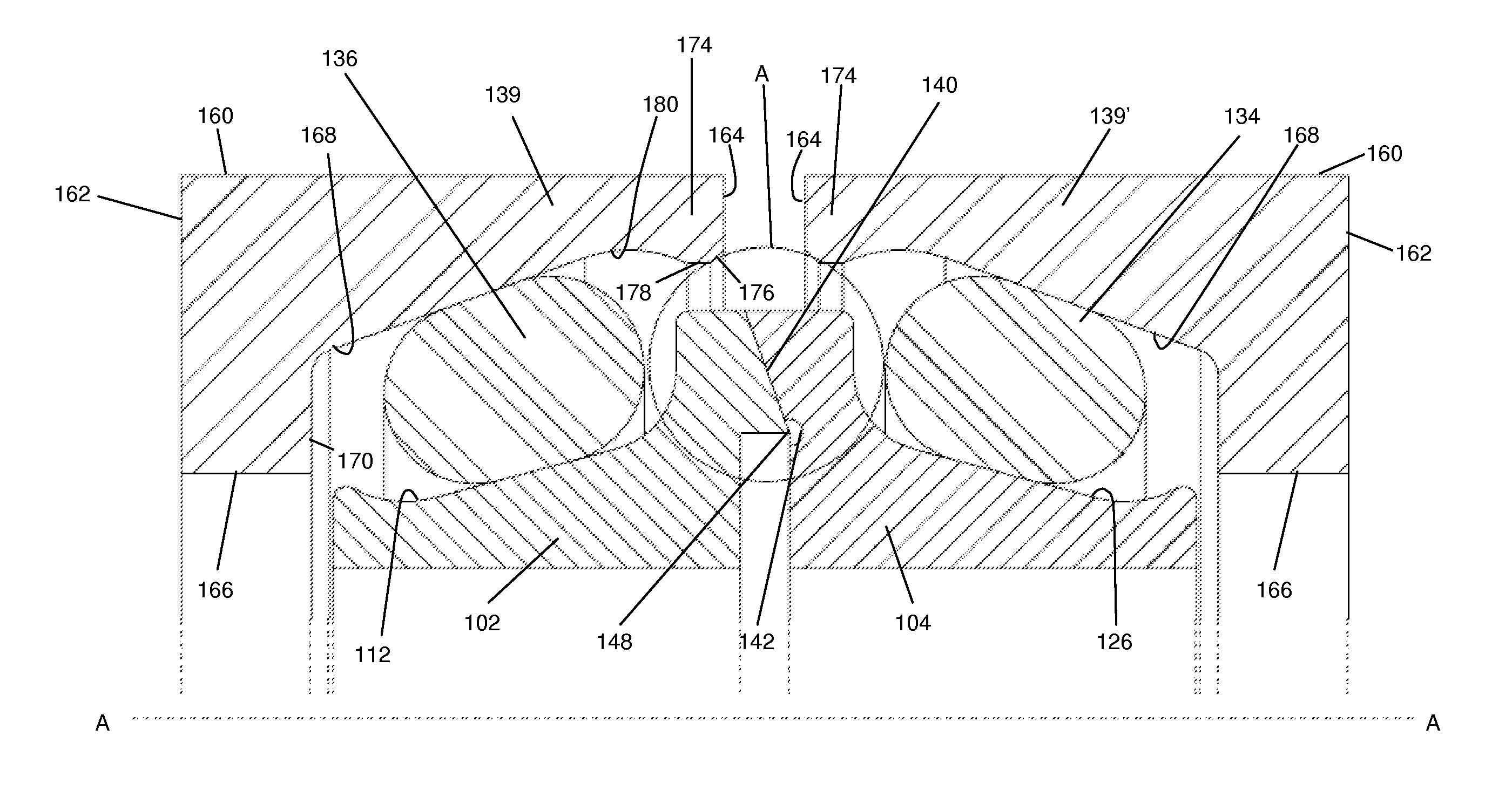
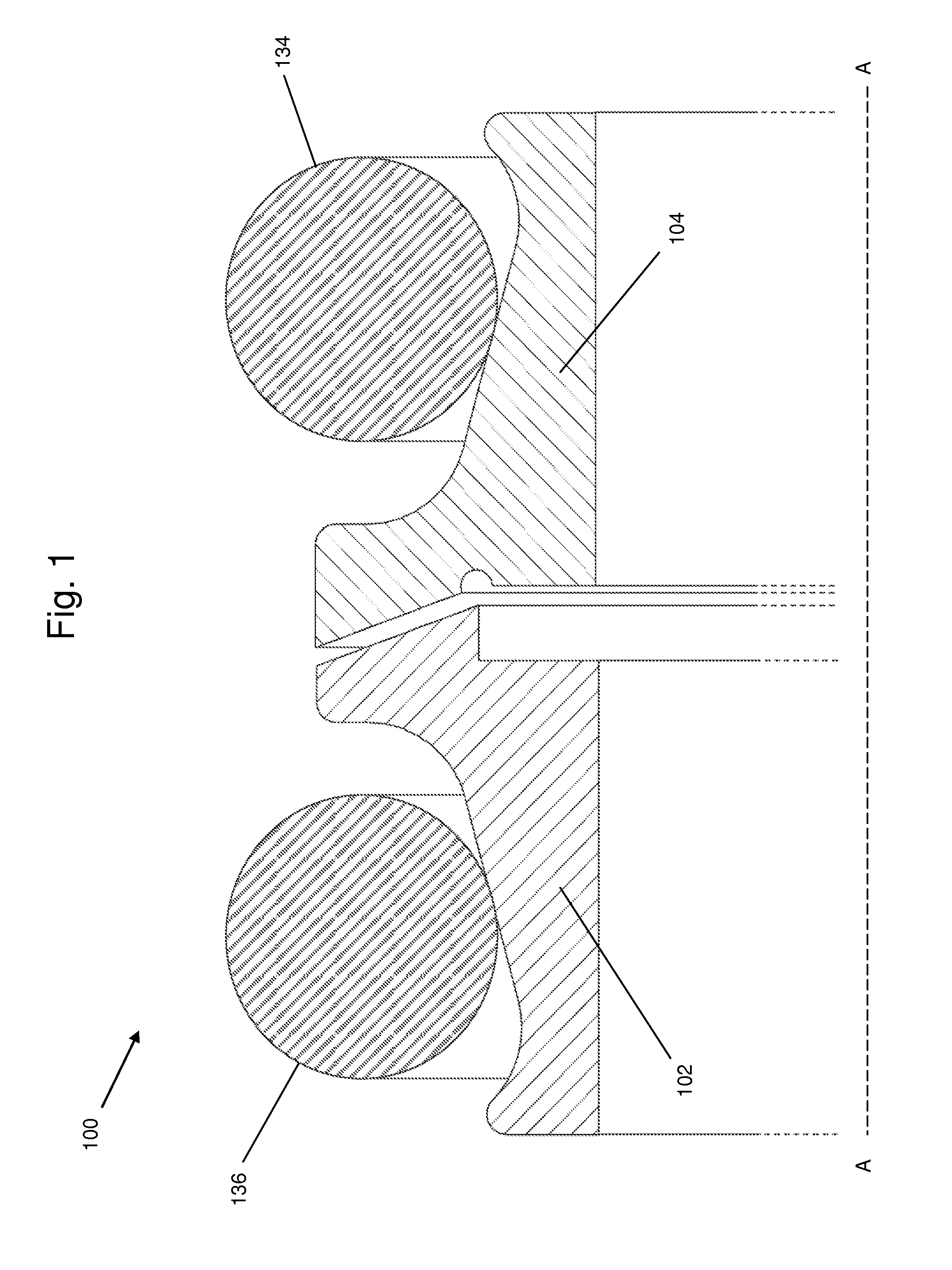
[0044]The only difference from the first embodiment is the replacement of the tubular housing 138 with first and second separate housing components 139, 139′, which are associated with seal rings 102 and 104 respectively. Housing components 139, 139′ are identical to one another and each comprises a metal annulus having a cylindrical outer face 160, a planar, annular outer end face 162 extending perpendicularly to the longitudinal axis A-A of the seal assembly, a planar, annular inner end face 164 extending radially inwardly from the inner end of the cylindrical outer face 160 and an aperture formed by a cylindrical face 166 extending perpendicularly to the outer end face 162.

[0045]The outer end face 162 is significantly wider than the inner face 164, and the radially inner face of each housing component 139, 139′ is formed into an inclined face 168 extending between a radially extending face 170 of a longitudinally outer shoulder 172 and a further shoulder 174 formed at the longitu...

second embodiment

[0050]The second embodiment also allows for a change in the “setting gap” between the opposed faces 164 of the housing component 139, 139′ while also ensuring the concentricity of the seal face contact when eccentricity of the housing components 139, 139′ occurs in installation or operation.

[0051]The composition of the seal rings 102 and 104 may comprise a cast iron alloy or a forged steel. However, the type and grade of metal composition of the seal rings 102 and 104 may be selected based on desired physical properties including, but not limited to, hardness, toughness and wear resistance. Further still, the seal rings 102 and 104 may be manufactured from dissimilar metals. Factors affecting the selection of materials include the ability to bond with coatings, cost and ability to be machined.

[0052]Finishing processes of the seal rings 102 and 104 may include grinding and / or lapping and / or turning. These machine processes may be different for different regions of the seal rings 102 ...


PUM

PropertyMeasurementUnit
cross-sectional lengthaaaaaaaaaa
durableaaaaaaaaaa
contact pressuresaaaaaaaaaa

Abstract

A seal assembly comprises a first ring and a second ring which are rotatable relative to each other about a longitudinal axis (A-A). A first annular seal surface is formed on the first ring and is inclined with respect to the longitudinal axis and a second annular seal surface is formed on the second ring and is complementarily inclined to, and in abutment with, said first annular seal surface on the first ring. An annular groove is formed in at least one of said first and second seal rings adjacent to the seal surface on said seal ring and preferably a portion of the other ring projects into, or to a location adjacent to, the annular groove.

Description

[0001]This application claims priority under 37 C.F.R. §119(a)-(d) to United Kingdom Patent Application No. 14 03898.8, filed Mar. 5, 2014, the disclosure of which is hereby incorporated by reference herein in its entirety.BACKGROUND OF THE INVENTION[0002]The present invention relates to seal assemblies and in particular, but not exclusively, to metal face seal assemblies.[0003]Metal face assemblies are used in a number of applications, for example in the oil and gas industry where they are operated in highly destructive or abrasive environments. Metal face seal assemblies often provide a seal between relatively rotating components, protecting against solid and liquid contaminants as well as providing leak proof retention of lubricants. Typically, they comprise a pair of confronting face seal rings of metal or other durable material. The seal rings rotate relative to one another in face-to-face contact to provide a positive face seal which retains lubricant and prevents foreign matt...

Claims


Application Information

Patent Timeline
Patent Type & Authority Applications(United States)
IPC IPC(8): F16J15/00F16J15/18F16J15/34
CPCF16J15/002F16J15/181F16J15/3404F16J15/3456F16J15/344F16J15/16F16J15/28
Inventor CRITCHLEY, ANDREW
Owner ERIKS IND SERVICES
Why Eureka
Try Eureka