
Electric household appliance remote monitoring system

a technology for monitoring systems and electric household appliances, applied in electric devices, instruments, transportation and packaging, etc., can solve the problems of power consumption of connected electric equipment and power consumption of the whole house, and achieve the effects of avoiding fire, avoiding anxiety, and avoiding the possibility of fir

Inactive Publication Date: 2015-09-10
NITTO DENKO CORP
View PDF1 Cites 67 Cited by
  • Summary
  • Abstract
  • Description
  • Claims
  • Application Information

AI Technical Summary

Benefits of technology

The present invention is a system for monitoring the operation of electric household appliances. It can detect abnormal operational conditions, degradation, or even potential hazards like electricity leakage. The system can then notify the user of the abnormality and provide information on repair and maintenance of the appliance. This way, users can receive timely service and prevent accidents caused by malfunctions. Additionally, the system can also help users save energy by introducing energy-efficient appliances or combining photovoltaic generation with the system.

Problems solved by technology

However, these techniques merely measure power consumption of connected electric equipment.
In addition, these meters measure power consumption of the whole house at intervals of several tens of minutes.

Method used


Image

  • Electric household appliance remote monitoring system
  • Electric household appliance remote monitoring system
  • Electric household appliance remote monitoring system

Examples


example

[0297]A device assuming an embedded outlet illustrated in FIG. 7 using four MOSFETs for each slot of the outlet was manufactured and connected to a fan.

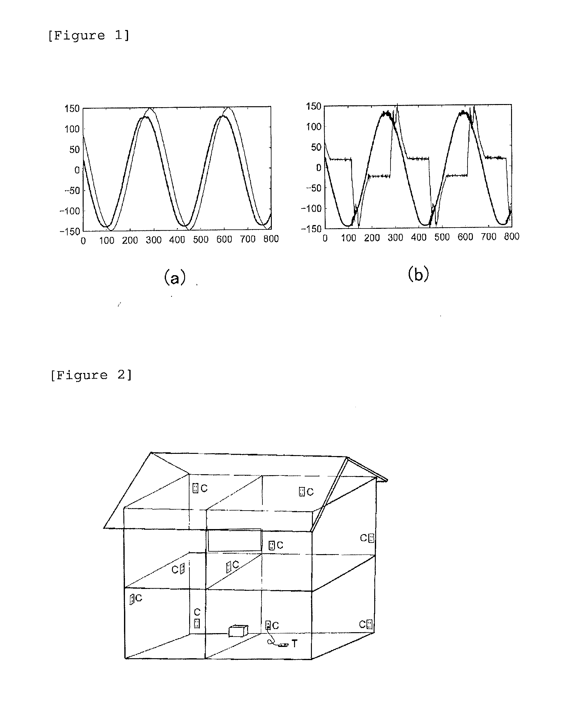
[0298]The fan was powered on to start rotation and operation of a motor. Assuming that the fan was continuously used, load was applied to blades of the fan so as to lower rotating speed of the motor. Data at this time is illustrated in FIG. 12.

[0299]In FIG. 12, a current waveform and a power waveform of the fan were measured. While, in a normal state, the waveforms appear as accurate sine waves as illustrated in an upper graph of FIG. 12, when load is applied to the blades to simulate a case where abnormality occurs at the motor, apparently, the power waveforms do not appear as sine waves as illustrated in a lower graph.

[0300]By comparing these voltage waveforms, it is possible to detect occurrence of abnormality in the connected fan based on a difference in the characteristic amounts such as patterns and peak power.


PUM


Abstract

An electric household appliance remote monitoring system including a smart tap to which one or two or more power plugs of electric equipment can be inserted, an electric household appliance incorporating a smart tap function, and a server is provided. The smart tap includes voltage waveform measuring means and / or current waveform measuring means and communication means. The server has a function of judging an operation state of each piece of connected electric equipment based on the voltage waveform and / or the current waveform received from the smart tap and, when detecting abnormality of the electric equipment, transmitting the detection to an external network.

Description

TECHNICAL FIELD[0001]The present invention relates to an electric household appliance remote monitoring system including a smart tap for an outlet, a tap, or the like, to which power plugs of various pieces of electric equipment and electric household appliances are connected.BACKGROUND ART[0002]A currently known system for supplying power to electric household appliance, intended to visualize power, reduce power consumption or manage power consumption will be described below.[0003]There is publicly known as disclosed in Patent Literature 1, a home energy management system including: power amount measuring means for measuring current power consumption indicating a power amount currently consumed in a dwelling unit; upper limit power amount setting and storage means which is capable of setting and storing an upper limit power amount indicating a maximum amount of an overall power amount which can be consumed in the dwelling unit; power management means for sequentially calculating cu...

Claims


Application Information

Patent Timeline
Patent Type & Authority Applications(United States)
IPC IPC(8): G01R21/00
CPCG01R21/00H04Q9/00G01R22/10Y04S40/121H02J13/00007H02J2310/70H02J13/00024H02J13/00026H02J13/00034Y02B90/20G05B15/02G05B2219/2613G05B2219/2639G01R11/00
Inventor HIEDA, YOSHIHIROBAN, NAOKITSUTSUMIUCHI, RYOJI
Owner NITTO DENKO CORP
Learn More