Aerodynamic device

a technology of aerodynamic devices and bending loads, which is applied in the direction of airflow influencers, wing adjustments, weight reduction, etc., can solve the problems of reducing the in-plane bending stiffness of the segment, the trailing edge section and the device, and achieves the reduction of the bending load on the device, the in-plane bending stiffness, and the effect of low in-plane bending stiffness

Active Publication Date: 2015-09-17
AIRBUS OPERATIONS LTD
View PDF8 Cites 8 Cited by
  • Summary
  • Abstract
  • Description
  • Claims
  • Application Information

AI Technical Summary

Benefits of technology

[0041]Having a relatively low in-plane bending stiffness on the trailing edge section reduces the in-plane bending stiffness of the device. Hence, if / when the device is deployed or is mounted away from the aerodynamic structure, the bending loads on the device are reduced. This allows the device to be supported by multiple support points (e.g. slat tracks). Hence, the device can be longer than it would be otherwise. This means that fewer devices are needed. For example, a single slat could be used to provide additional lift over the length of a wing.
[0042]The effect of this invention may be demonstrated by consideration of the bending stiffness of a typical slat. Modelled as an equivalent homogeneous beam, the typical slat may have an out-of-plane spanwise bending stiffness of 5.8×106 mm4 and an in-plane bending stiffness of 47.3×106 mm4. In the present invention, the out-of-plane spanwise bending stiffness of the trailing edge may be reduced by a factor of up to, say 10, to 5.8×105 mm4. As result of modifying the trailing edge out-of-plane spanwise bending stiffness, the in-plane bending stiffness of the whole slat is reduced to 10.4×106 mm4, nearly a five-fold decrease. The out-of-plane spanwise bending stiffness of the whole slat may be maintained by modifying the leading edge section, for example by increasing the stiffness of a D-nose boom in the leading edge section. The out-of-plane chordwise bending stiffness may be maintained or manipulated as an independent variable to the out-of-plane spanwise bending stiffness.

Problems solved by technology

This reduces the in-plane bending stiffness of the segment. and therefore the trailing edge section and the device as a whole.

Method used


Image

  • Aerodynamic device
  • Aerodynamic device
  • Aerodynamic device

Examples


first embodiment

[0096]FIG. 3 shows a schematic perspective view of part of a skin sheet 260 of a trailing edge section of a slat according to the invention. The axes shown on this Figure show a spanwise direction 261 extending along the length of the slat, a chordwise direction 262 extending along the width of the slat and an out-of-plane direction 263 extending upwards away from the slat.

[0097]The skin sheet 260 is part of a sandwich structure of the trailing edge section comprising a core sandwiched between two such skin sheets. The skin sheet 260 comprises a number of composite layers layed out one above the other in the out-of-plane 263 direction. The layers include a first lower layer 266, a second layer 265 and a third upper layer 264. Each layer comprises a number of carbon fibres, orientated in a particular direction. In the first layer 266, the fibres 266a are orientated substantially in the chordwise direction 262. In the second layer 265, the fibres 265a are orientated in the spanwise di...

second embodiment

[0103]FIG. 4 shows a schematic perspective view of part of a skin sheet 360 of a trailing edge section of a slat according to the invention. The directions shown on this Figure show a spanwise direction 361 extending along the length of the slat, and a chordwise direction 362 extending along the width of the slat.

[0104]The skin sheet 360 is part of a sandwich structure of the trailing edge section comprising a core sandwiched between two such skin sheets. The skin sheet 360 comprises a number of “zig-zag” corrugations 364, corrugated (“folded”) in the spanwise direction 361 so as to create channels running in the chordwise direction 362. The skin sheet 360, therefore, is anisotropic, i.e. it has different stiffness characteristics in the chordwise and spanwise directions. The material used for the core is honeycomb and is also anisotropic, i.e. it has different stiffness characteristics in the chordwise and spanwise directions.

[0105]This means that the spanwise stiffness of the trai...

third embodiment

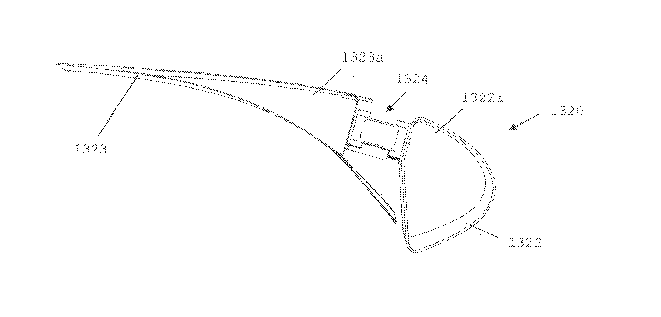
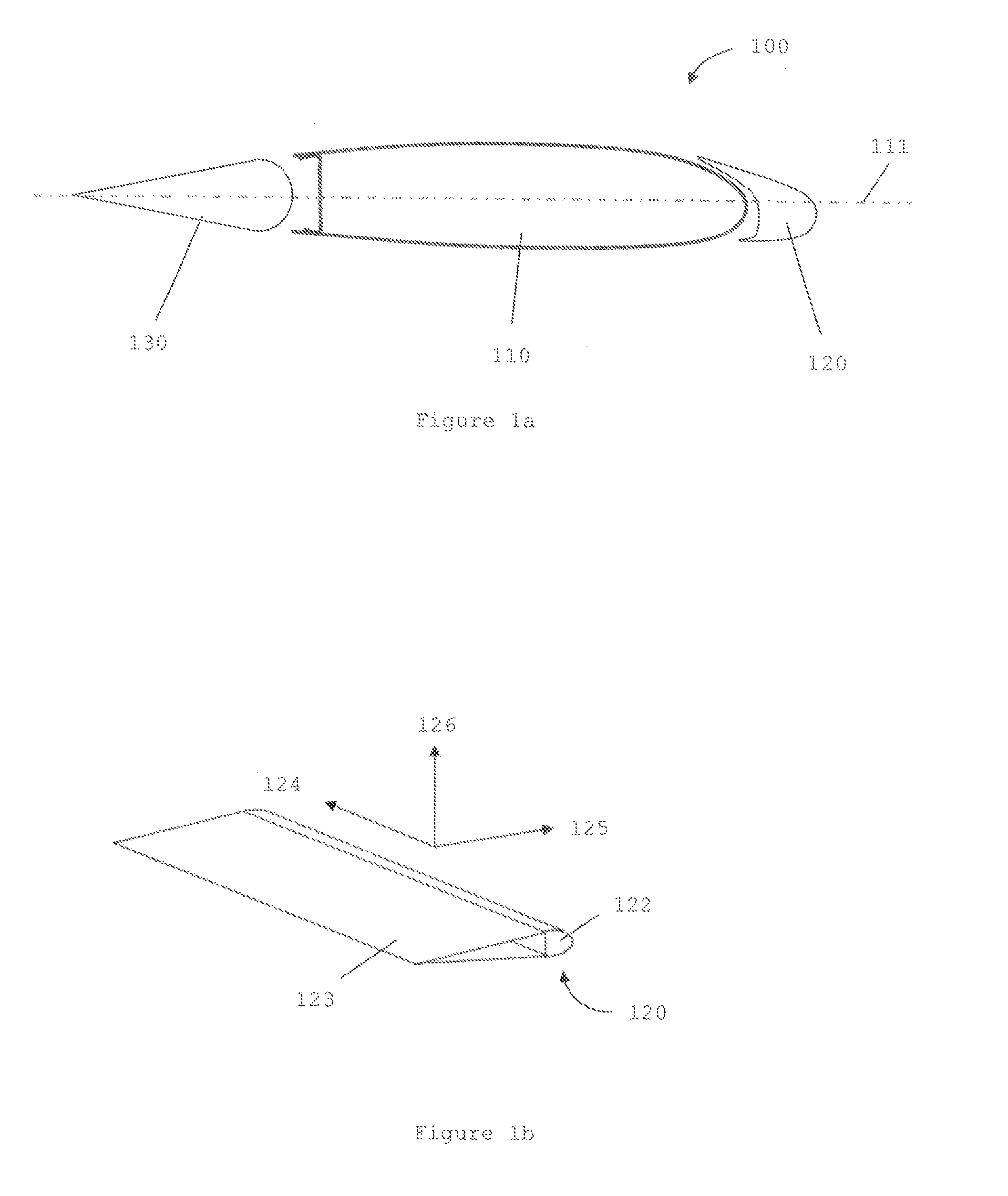
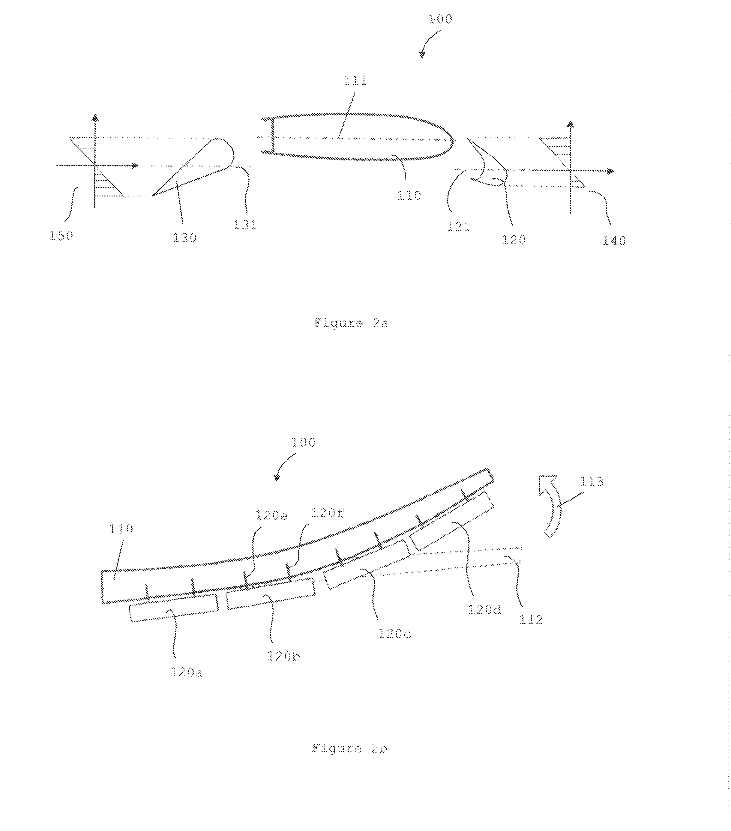
[0107]FIG. 5a shows a schematic perspective view of a slat 420 according to the invention. The slat 420 comprises a D-nose leading edge section 422 and a wedge shaped trailing edge section 423. The trailing edge section 423 is a sandwich structure with a core sandwiched between two skins. The trailing edge section 423 has four chordwise slots 424, 425, 425, 427 in it, effectively dividing the trailing edge portion of the trailing edge section 423 into 5 segments. Each slot extends though the height of the slat, from the trailing edge, chordwise to a forward location (but still within the trailing edge wedge section 423) of the slat. Each slot 424, 425, 426, 427 comprises an elongate section 424a extending chordwise from the trailing edge, ending in a rounded “nodule”424b. The leading edge section 422 also comprises an attachment structure (not shown) for attaching the slat 420 to a wing primary structure.


PUM


Abstract

The invention provides an aerodynamic device configured for being mounted to an aerodynamic structure of an aircraft, the aerodynamic device having a spanwise length, a chordwise width, a leading edge section along a leading edge of the device, for being mounted to the aerodynamic structure of the aircraft, and a trailing edge section along a trailing edge of the device, for providing a required aerodynamic profile, wherein a first chordwise extending segment of the trailing edge section is moveable in a spanwise direction with respect to the leading edge section or with respect to a second chordwise extending segment of the trailing edge section.

Description

RELATED APPLICATIONS[0001]The present application claims priority of Great Britain Application Number 1404397.0, filed Mar. 12, 2014, the disclosure of which is hereby incorporated by reference herein in its entirety.BACKGROUND OF THE INVENTION[0002]The present invention concerns aerodynamic devices, such as slats, ailerons, elevators, spoilers, flaps, Krueger flaps and rudders. More particularly, but not exclusively, this invention concerns aerodynamic devices for being rotatably mounted to an aerodynamic structure, such as a wing, horizontal tailplane or vertical tailplane, of an aircraft, the aerodynamic device having a spanwise length, a chordwise width, a leading edge section along a leading edge of the device, for being rotatably mounted to the aerodynamic structure of the aircraft, and a trailing edge section along a trailing edge of the device, for providing a required aerodynamic profile. The invention also concerns an aircraft comprising such an aerodynamic device.[0003]Ty...

Claims


Application Information

Patent Timeline
Patent Type & Authority Applications(United States)
IPC IPC(8): B64C3/50B64C9/22B64C9/16B64C21/02
CPCB64C3/50B64C9/16B64C9/22B64C21/02B64C9/00Y02T50/40B64C3/38
Inventor BRAKES, DAVID
Owner AIRBUS OPERATIONS LTD
Why Eureka
Try Eureka