Rotary device having a radial magnetic coupling

a radial magnetic coupling and rotary device technology, applied in the direction of machines/engines, mechanical equipment, positive displacement liquid engines, etc., can solve the problems of increasing the total radial gap between the magnets, wasting power, and affecting the equipment and/or fluid within the equipment, so as to reduce the axial length of the rotary device, reduce the cost, and reduce the cost

Active Publication Date: 2015-09-17
PEOPLEFLO MFG
View PDF12 Cites 17 Cited by
  • Summary
  • Abstract
  • Description
  • Claims
  • Application Information

AI Technical Summary

Benefits of technology

[0022]The disclosure provides rotary devices that may include numerous advantageous aspects for rotary magnetically coupled devices, such as, a bushing that serves three purposes, a stationary canister that serves three purposes, the stationary canister being made of two separate parts including a substantially cylindrical portion and a canister end cap portion, and the two separate parts optionally being constructed of the same or different materials, with the stationary canister being held in compression through the substantially cylindrical portion between the front and rear casing portions when the device is fully assembled.
[0029]Utilization of the subject matter in the present disclosure can lead to construction of rotary devices that are more compact, since the magnet coupling and bushings are essentially packaged within the same axial space. Thus, the axial length of rotary devices can be reduced, which may have advantages resulting in the ability to use longer magnets for greater torque generation within the same axial space. Alternatively, this may provide an option to use many smaller and / or less expensive components relative to a rotary device having a conventional magnet coupling. This, in turn, can result in rotary devices that require a smaller volume or space for mounting, and that are of lighter weight and are easier to handle.

Problems solved by technology

These eddy currents convert some of the transmitted power into heat, which wastes power and often has detrimental effects on the equipment and / or the fluid within the equipment.
This eliminates the eddy current heating, but usually results in a much thicker cylindrical portion between the magnets, which increases the total radial gap between the magnets and therefore reduces the torque created for a given volume of magnet material.
For a rotor that is inside the fluid chamber, this usually requires a separate component or components, such as a sleeve or coating between the magnets and the canister, which unfortunately increases the total radial gap between the magnets, and therefore, reduces torque.
The bushing components usually are not positioned within the radial gap between the magnets, since this would greatly increase the total radial gap between the magnets, and therefore, greatly reduce torque.
When a bushing is positioned at only one end, the rotor support is cantilevered, which disadvantageously allows much more deflection of the rotor.
However, because the bushings typically are positioned beyond either end of the magnets, lengthening the bearing surfaces would disadvantageously require substantially greater axial space.

Method used


Image

  • Rotary device having a radial magnetic coupling
  • Rotary device having a radial magnetic coupling
  • Rotary device having a radial magnetic coupling

Examples


Embodiment Construction

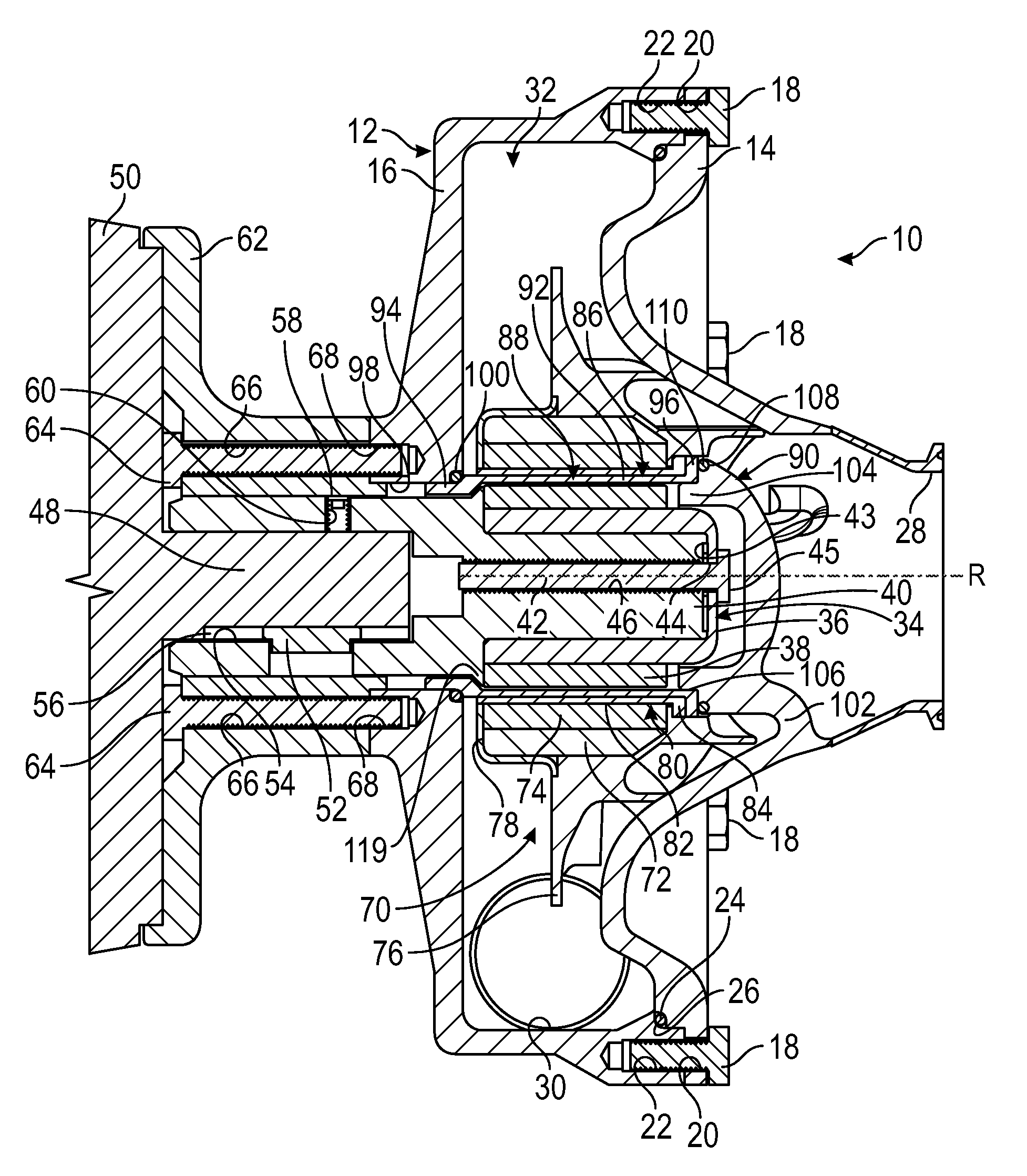
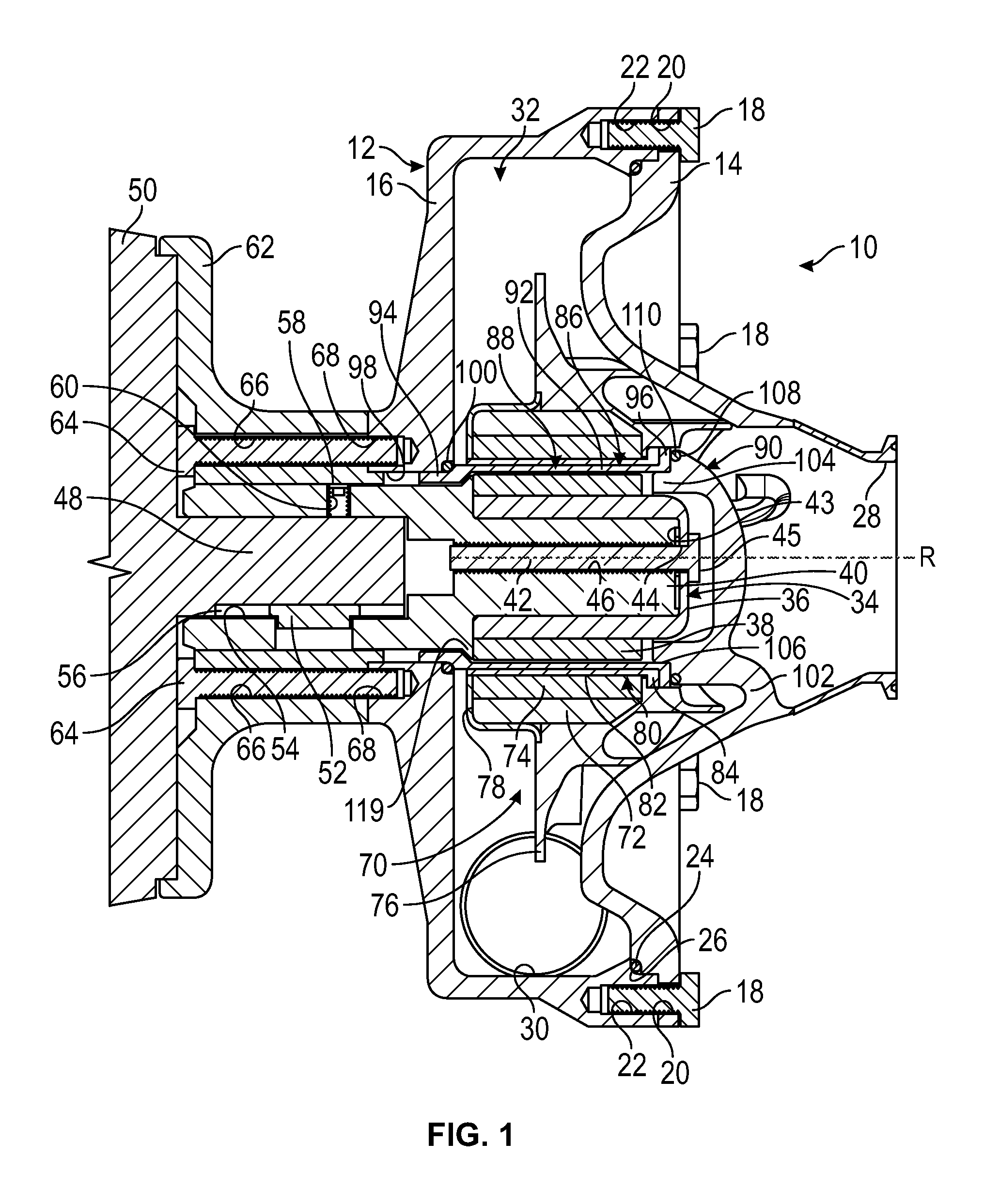
[0051]Referring generally to FIGS. 1-7C, it will be appreciated that a rotary device 10 in the configuration of a pump, and component parts thereof, are shown. The rotary device 10 includes a casing 12 having a casing front portion 14 connected to a casing rear portion 16. The connection may be made, for example, by using fasteners 18, shown as threaded bolts, which pass through bores 20 in the casing front portion 14 and into threaded bores 22 in the casing rear portion 16. The casing front portion 14 also is sealed to the casing rear portion 16 by use of a static seal 24, such as an elastomeric O-ring, or preformed or liquid gasket or the like, which is positioned in a seal retaining well 26 in the casing front portion 14.

[0052]The casing 12 may be constructed of rigid materials, such as steel, stainless steel, cast iron or other metallic materials, or structural plastics or the like. However, it will be appreciated that the casing 12 and all surfaces that contact the fluid that w...


PUM


Abstract

Rotary devices having a casing and an inner drive portion of a magnet coupling disposed inside of a rotor assembly are disclosed. The inner drive portion and rotor assembly are disposed within the casing and rotatable about a rotational axis. The rotor assembly includes a bushing between the magnets of the rotor assembly and a stationary canister is sealed to the casing and separates an internal fluid chamber within the casing from the inner driven portion. The stationary canister can be of multi-piece or unitary construction and is held in position by a front portion of the casing.

Description

BACKGROUND OF THE INVENTION[0001]1. Field of the Invention[0002]The present invention generally relates to radial magnetic couplings that may be used in rotary equipment, such as pumps, mixers and compressors, and more particularly to rotary devices having a radial magnetic coupling wherein the magnetic coupling transmits torque from one component to another through a stationary fluid barrier.[0003]2. Discussion of the Prior Art[0004]In many rotary devices, such as pumps, mixers and compressors, it is desirable to avoid rotating seals. Magnetic couplings have been developed with a magnet coupling that utilizes a driven component and a drive component with the driven component being driven via a non-contacting permanent magnet coupling in a radial magnet orientation. Such equipment frequently is referred to as being sealless, but actually includes inner and outer magnets separated by a canister that is sealed with one or more static seals.[0005]Radial magnetic couplings that utilize ...

Claims


Application Information

Patent Timeline
Patent Type & Authority Applications(United States)
IPC IPC(8): F04D13/02F04D1/04H02K49/10
CPCF04D13/025F04D1/04H02K49/106F04D13/026
Inventor BLANKEMEIER, WILLIAM R.SHAFER, CLARK J.TRNINICH, RADOSAVMURPHY, JORGE G.NARD, JAMES A.SEXTON, JASON M.
Owner PEOPLEFLO MFG
Why Eureka
Try Eureka