Microelectromechanical sensing structure for a pressure sensor including a deformable test structure

a micro-electromechanical and sensor technology, applied in the direction of fluid pressure measurement, fluid pressure measurement by electric/magnetic elements, instruments, etc., can solve the problems of reduced parallelization capacity and high cos

Active Publication Date: 2015-09-17
STMICROELECTRONICS INT NV
View PDF8 Cites 10 Cited by
  • Summary
  • Abstract
  • Description
  • Claims
  • Application Information

AI Technical Summary

Problems solved by technology

In general, the test systems so far known enable effective testing of sensing structures of a known type; however, ac

Method used


Image

  • Microelectromechanical sensing structure for a pressure sensor including a deformable test structure
  • Microelectromechanical sensing structure for a pressure sensor including a deformable test structure
  • Microelectromechanical sensing structure for a pressure sensor including a deformable test structure

Examples


Embodiment Construction

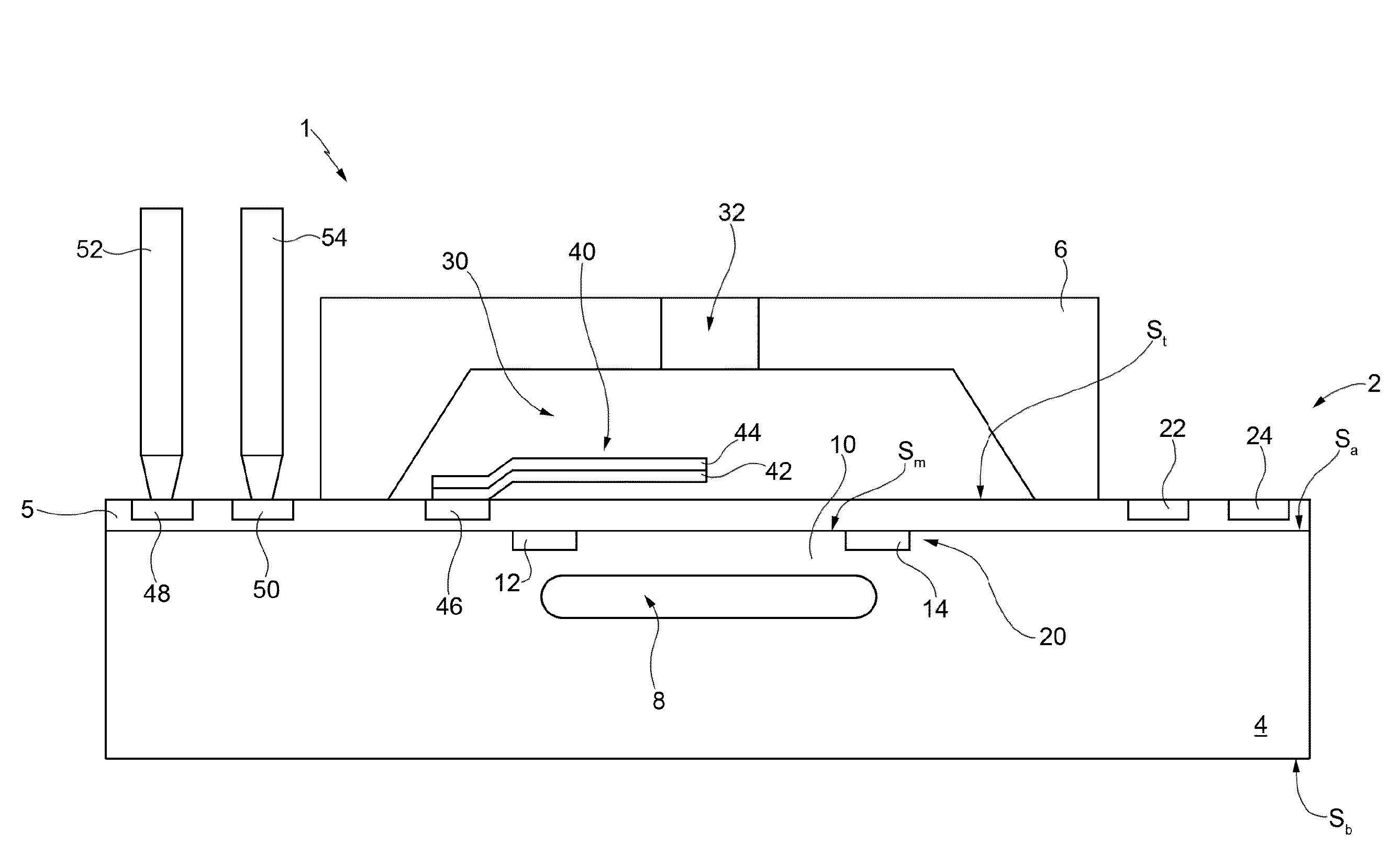
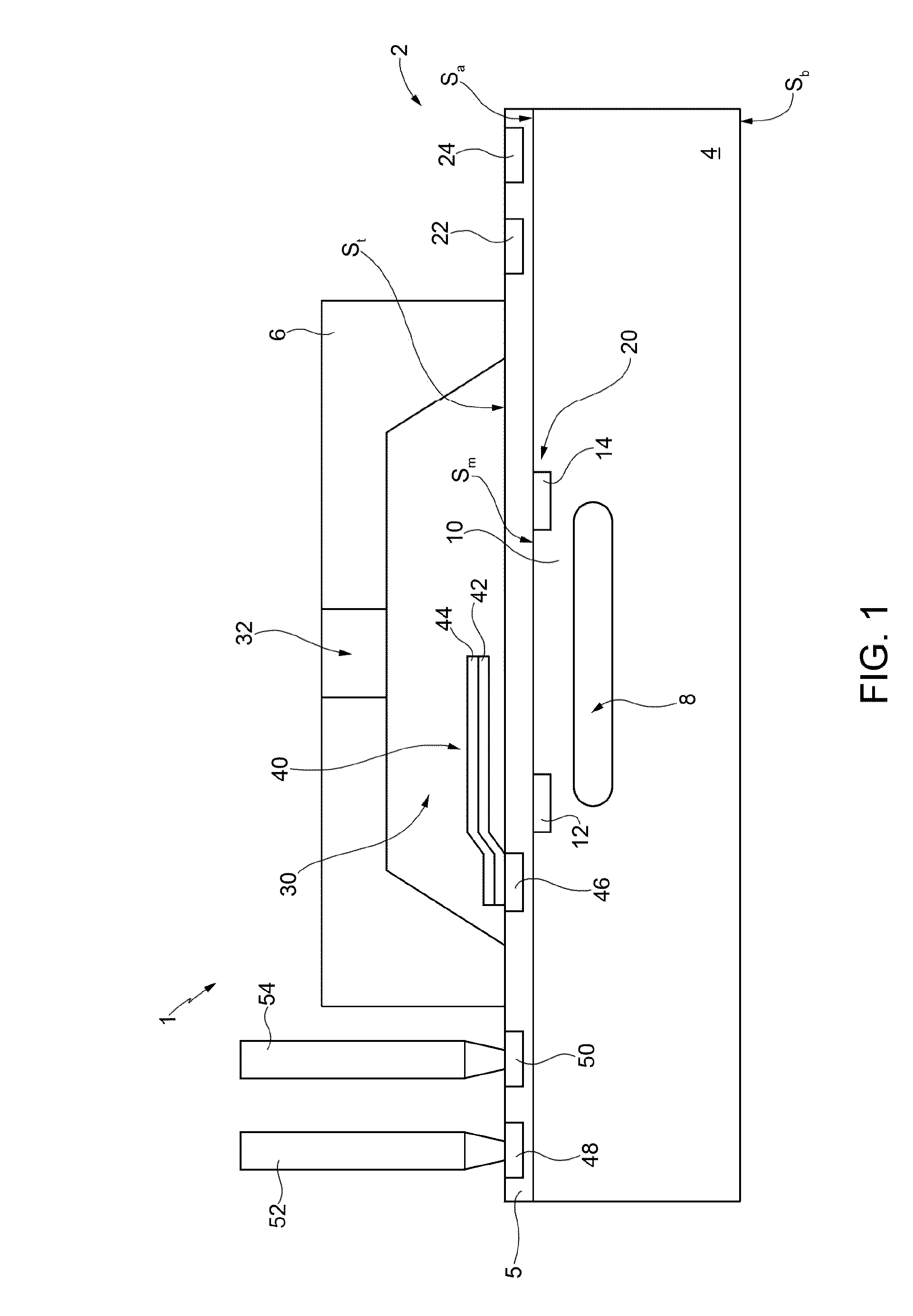
[0023]FIG. 1 shows a pressure sensor 1, which comprises a sensing structure 2, which includes a semiconductor body 4, a top region 5, and a cap 6.

[0024]The semiconductor body 4 comprises a substrate (not shown) and may further comprise one or more epitaxial layers (not shown). In addition, the semiconductor body 4 delimits a cavity 8 of a buried type, referred to herein as “sensing cavity”8. In particular, without this implying any loss of generality, the semiconductor body 4 forms a membrane 10, which delimits the sensing cavity 8 at the top and is designed to undergo deformation as a function of the pressure exerted on the membrane itself.

[0025]The semiconductor body 4 is delimited at the top and at the bottom by a top surface Sa and a bottom surface Sb, respectively, referred to hereinafter as “top body surface” Sa and “bottom body surface” Sb. Furthermore, the top body surface 5, forms the surface that delimits the membrane 10 at the top, i.e., the surface of the membrane opposi...


PUM

PropertyMeasurementUnit
Temperatureaaaaaaaaaa
Pressureaaaaaaaaaa
Electrical conductivityaaaaaaaaaa

Abstract

A microelectromechanical sensing structure having a membrane region including a membrane that undergoes deformation as a function of a pressure and a first actuator that is controlled in a first operating mode and a second operating mode, the first actuator being such that, when it operates in the second operating mode, it contacts the membrane region and deforms the membrane in a way different from when it operates in the first operating mode.

Description

BACKGROUND[0001]1. Technical Field[0002]The present disclosure relates to a microelectromechanical sensing structure for a pressure sensor, which includes a test structure that is at least in part deformable.[0003]2. Description of the Related Art[0004]As is known, there are today available pressure sensors such as, for example, the so-called sensors of the MEMS (microelectromechanical systems) type.[0005]Each MEMS pressure sensor comprises a sensitive structure of a MEMS type and a reading electronics.[0006]The sensitive structure, which is also known as “sensing structure”, typically forms a cavity delimited in part by a membrane and is designed to generate an electrical quantity (for example, a capacitive or resistive variation) indicating a pressure. Instead, the reading electronics are designed to carry out appropriate operations of processing of this electrical quantity for supplying an electrical output signal, whether analog (for example, a voltage) or digital. The electrica...

Claims


Application Information

Patent Timeline
IPC IPC(8): G01L9/00
CPCG01L9/0054G01L27/002Y10T29/42G01L9/0052G01L9/0055
Inventor PAGANI, ALBERTO
Owner STMICROELECTRONICS INT NV
Why Eureka
Try Eureka