Synchronized infrared beacon / infrared detection system

Inactive Publication Date: 2015-09-17
FLIR SYST INC
View PDF3 Cites 33 Cited by
  • Summary
  • Abstract
  • Description
  • Claims
  • Application Information

AI Technical Summary

Problems solved by technology

Unfortunately, this equipment leaves military personnel visible using inexpensive, low-level night vision or thermal imaging technology that is now available to insurgents.

Method used


Image

  • Synchronized infrared beacon / infrared detection system
  • Synchronized infrared beacon / infrared detection system
  • Synchronized infrared beacon / infrared detection system

Examples


example 1

Comparison of Beacon Systems

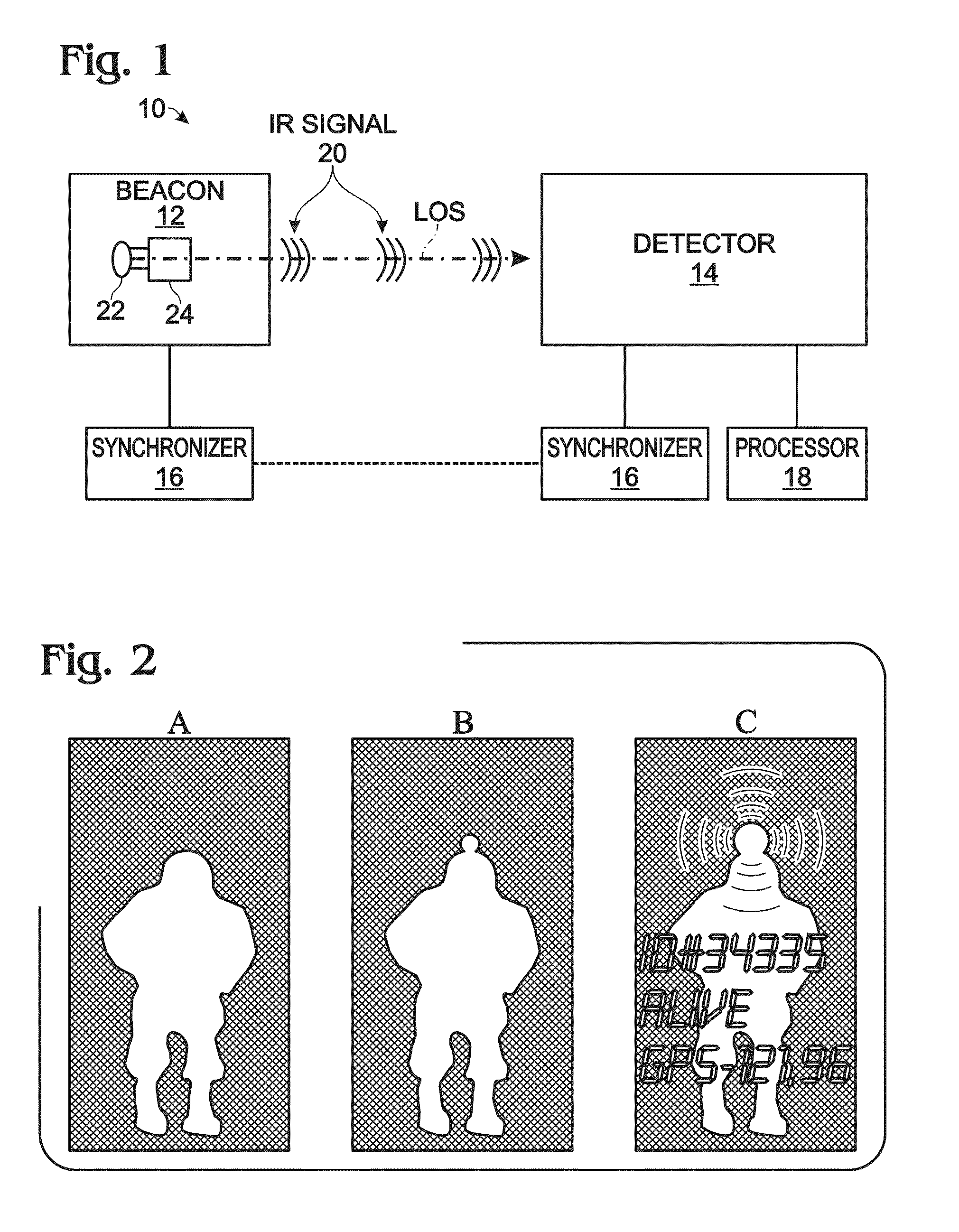
[0046]This example compares night vision images obtained using different beacon systems; see FIG. 2. Specifically, FIG. 2 shows three schematic thermal images of a soldier. In these images, the relatively warmer soldier is visible as a light silhouette, due to thermal emissions, against a relatively cooler dark background. Panel A shows the soldier with no beacon (silhouette only). Panel B shows the soldier with an existing helmet-mounted continuous beacon. This beacon alters the thermal profile of the soldier and is visible, when the soldier is upright, as an extension of the soldier's silhouette above the soldier's helmet. Panel C shows the soldier with a helmet-mounted flashing beacon synchronized with an infrared imaging system, in accordance with aspects of the present disclosure. This beacon, which may be detected in an entirely different wavelength regime than that used to collect the image, is portrayed in this example as an overlay that may inclu...

example 2

Exemplary Synchronization Protocols

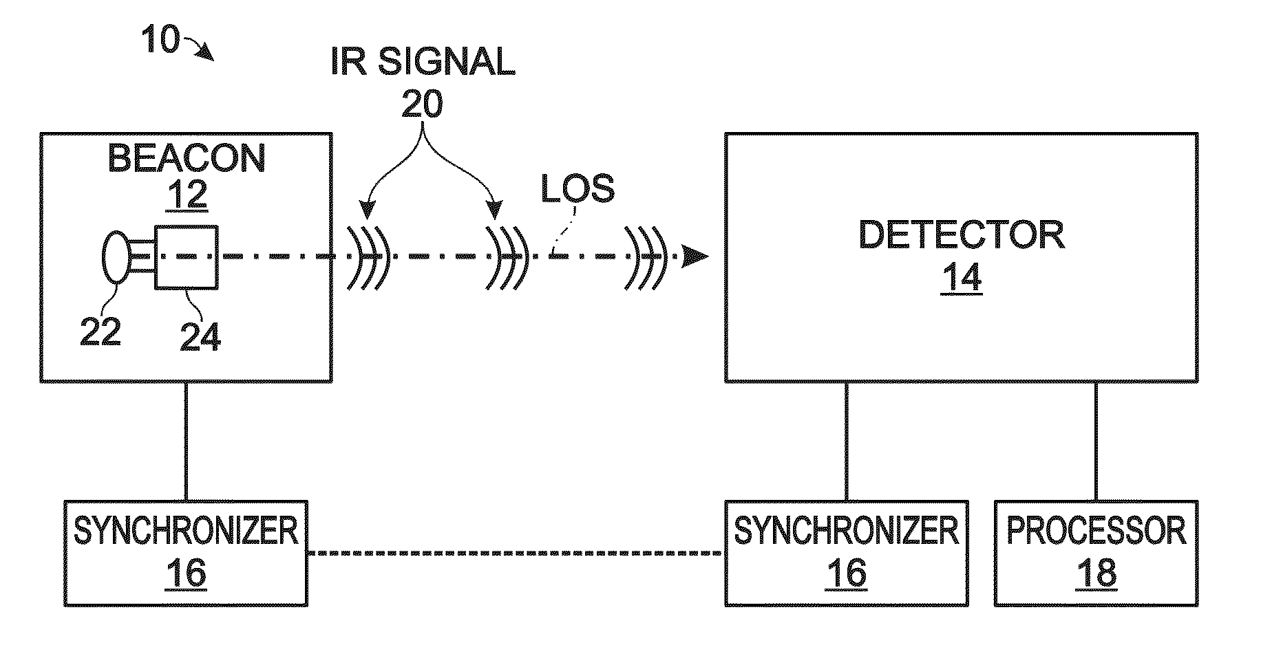
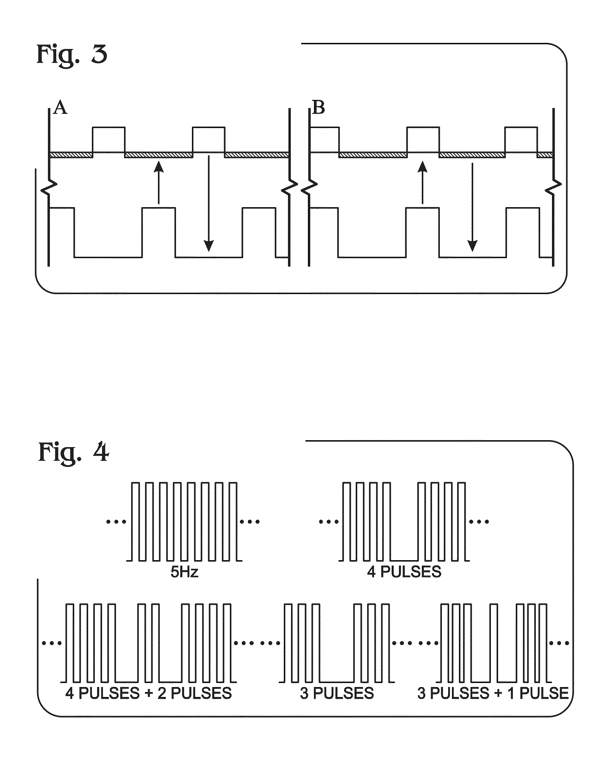
[0047]This example describes exemplary protocols for synchronizing an infrared beacon and an infrared camera; see FIG. 3. Specifically, FIG. 3 shows schematic representations of two such synchronization protocols. Panel A shows a first protocol: in synch, half periodicity delay; matching on-to-on times between infrared beacon and infrared detector. Panel B shows a second protocol: in synch, zero delay; matching on-and-off times between infrared beacon and infrared detector. More generally, the synchronizer may use any suitable or desired protocols, depending on the emitter, the detector, the type of information to be captured and analyzed, and so on.

[0048]In special situations, for example when synchronization is denied or is intermittent, or when the frequency of the beacon signal frequency is low, among others, data encoding and decoding and communication are still possible using the beacon / detector system. The processor can sample the received d...

example 3

Exemplary Pulse Patterns

[0049]This example describes exemplary pulse patterns representing beacon emissions; see FIG. 4. Specifically, FIG. 4 shows five such pulse patterns, all at the same arbitrary frequency. The top left panel shows a constant pattern: on, off, on, off, and so on (e.g., at a fixed frequency, such as 5 Hz). The top right panel shows a variable pattern: four pulses on, one pulse off, and then repeating. The bottom left panel shows another variable pattern: four pulses on, one pulse off, two pulses on, one pulse off, and then repeating. The bottom center panel shows yet another variable pattern: three pulses on, one pulse off, and then repeating. The bottom right panel shows still yet another variable pattern: three pulses on, one pulse off, one pulse on, one pulse off, and then repeating. These patterns are not exhaustive. For example, the off times may be variable and / or the patterns themselves may be variable (e.g., mixing schemes shown in the drawing). Generally...


PUM


Abstract

A synchronized infrared beacon/infrared detector system. The system may include (A) an infrared beacon module configured to generate a time-varying encoded infrared signal, (B) an infrared detector module configured to capture the encoded infrared signal generated by the beacon module, (C) a synchronizer configured to generate a synchronization signal that controls timing of the beacon module and the detector module, and (D) a processor, in communication with the detector module, configured to analyze the infrared signal captured by the detector module. The infrared signal may be modulated at frequencies undetectable by human vision. The synchronizer signal may be produced independent of the capture of, and without input from, the infrared signal.

Description

CROSS-REFERENCE TO PRIORITY APPLICATIONS[0001]This application is a continuation-in-part of PCT Patent Application Serial No. PCT / US2013 / 070619, filed Nov. 18, 2013, which in turn is based upon and claims the benefit under 35 U.S.C. §119(e) of U.S. Provisional Patent Application Ser. No. 61 / 727,612, filed Nov. 16, 2012. Each of these priority applications is incorporated herein by reference in its entirety for all purposes.CROSS-REFERENCES TO OTHER MATERIALS[0002]This application incorporates by reference in their entireties for all purposes the following U.S. patent documents: U.S. Patent Application Publication No. US 2009 / 0324015, published Dec. 31, 2009; U.S. Pat. No. 7,649,174; and U.S. Pat. No. 7,973,696. In particular, the system described herein may be used for any and all of the applications, and with any and all of the sub-components, described in the '015 publication.INTRODUCTION[0003]Personnel, vehicles, cargo and aircraft are often marked and tracked, for various purpos...

Claims


Application Information

Patent Timeline
Patent Type & Authority Applications(United States)
IPC IPC(8): H04B10/11
CPCH04B10/11F41H1/00F41H13/00F41J5/08G01S17/74
Inventor PUSCASU, IRINAPOIRIER, BRUCE ALLEN
Owner FLIR SYST INC
Why Eureka
Try Eureka