Luminaire and visible light communication system using same

Active Publication Date: 2015-09-17
PANASONIC INTELLECTUAL PROPERTY MANAGEMENT CO LTD
View PDF3 Cites 56 Cited by
  • Summary
  • Abstract
  • Description
  • Claims
  • Application Information

AI Technical Summary

Benefits of technology

[0006]It is an object of the present invention to provide a luminaire, which can suppres

Problems solved by technology

In this case, when a receiver is at a location capable of receiving the optical si

Method used


Image

  • Luminaire and visible light communication system using same
  • Luminaire and visible light communication system using same
  • Luminaire and visible light communication system using same

Examples


embodiment 1

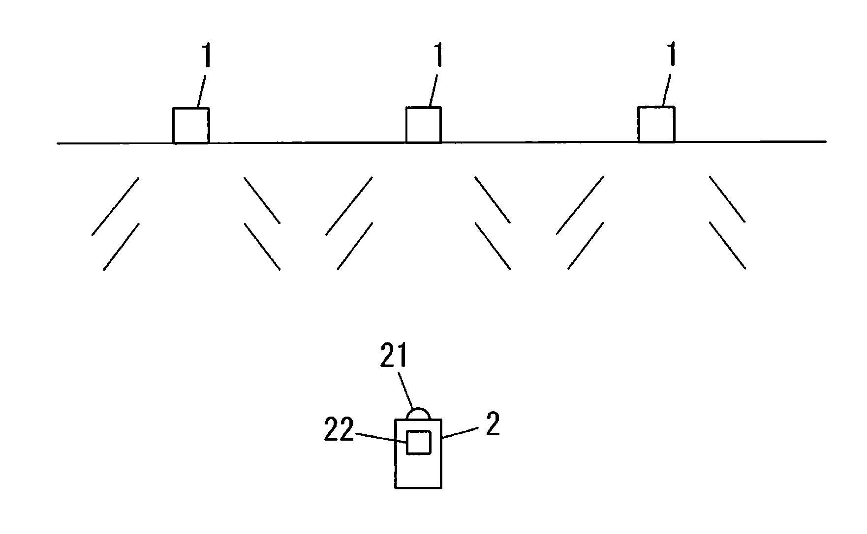
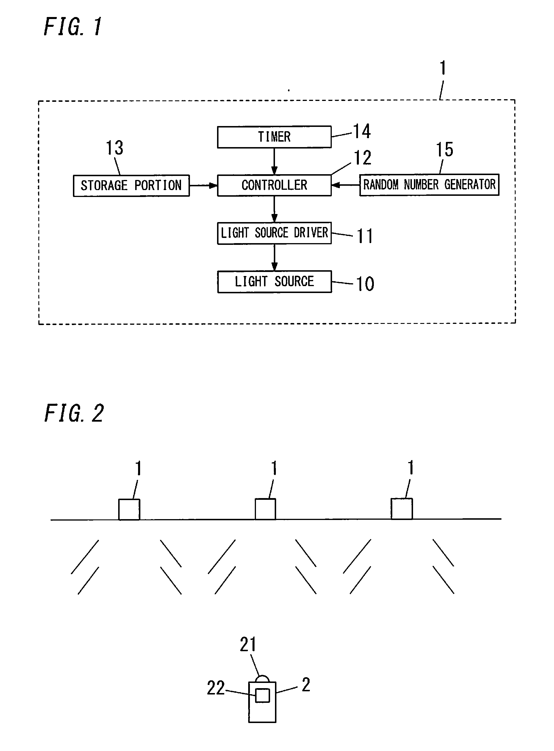
[0020]As shown in FIG. 1, a luminaire 1 of the embodiment includes an electric light source 10, a light source driver 11 configured to turn on the light source 10, and a controller 12 configured to control the light source driver 11.

[0021]For example, when the light source 10 is a DC light source such as a light-emitting diode, the light source driver 11 may include a well-known DC power supply circuit that is configured to turn on the light source 10, using DC power obtained by converting AC power received from an external.

[0022]The luminaire 1 further includes a storage portion 13, a timer 14 and a random number generator 15. The storage portion 13 is configured to store information to be transmitted with an optical signal. The timer 14 is configured to output a prescribed electric signal (hereinafter, referred to as a “notification signal”) to the controller 12, whenever a state where the light source 10 is in ON and no optical signal is transmitted is kept for a prescribed time ...

embodiment 2

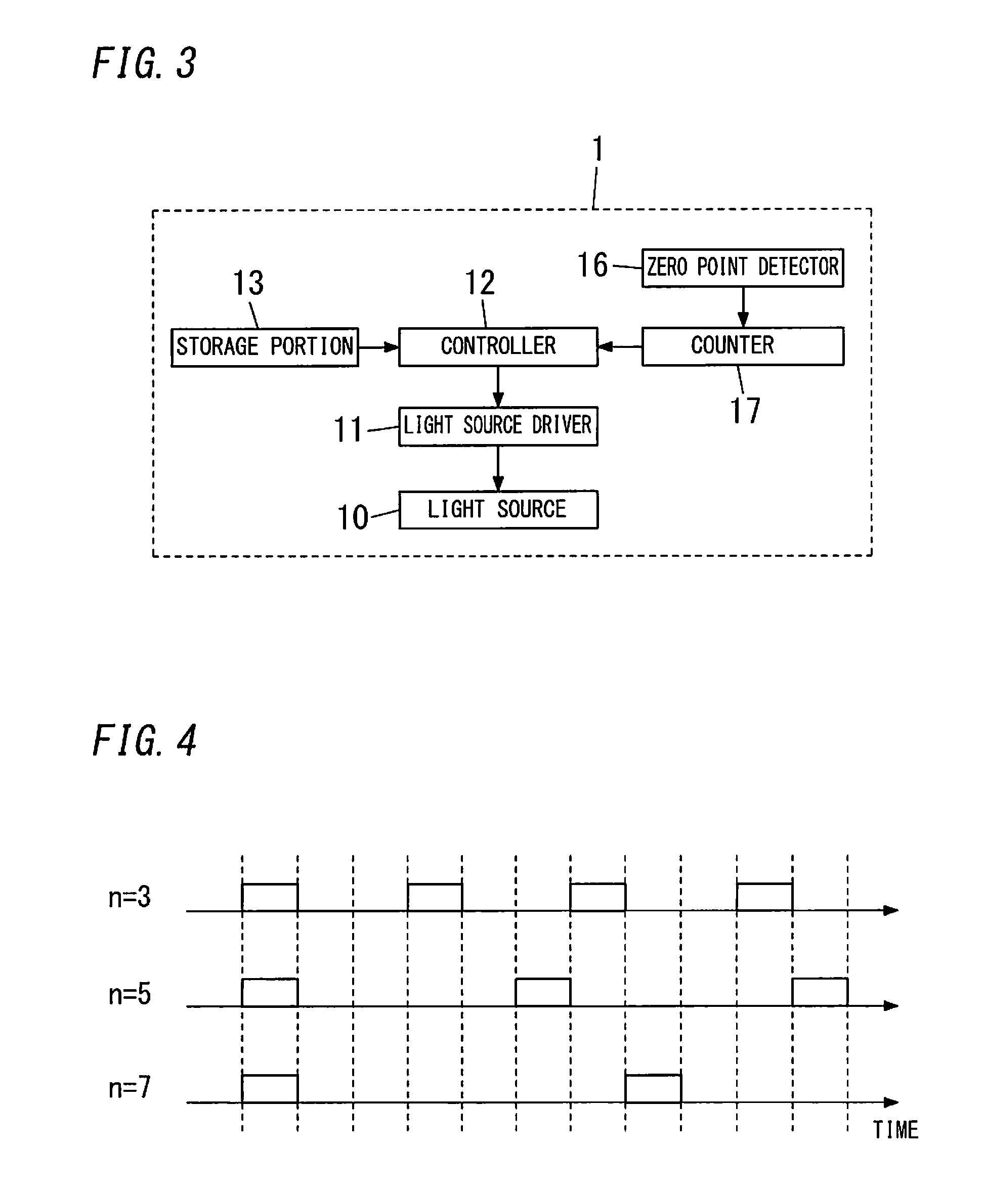
[0030]As shown in FIG. 3, a luminaire 1 of the embodiment is different from that of Embodiment 1 in that a zero point detector 16 and a counter 17 are provided, instead of the timer 14 and the random number generator 15. Note that, components similar to those of Embodiment 1 are assigned with same reference signs and the explanation thereof will be omitted.

[0031]Similarly to Embodiment 1, the luminaire 1 of the embodiment includes a light source 10, a light source driver 11 and a controller 12.

[0032]For example, when the light source 10 is a DC light source such as a light-emitting diode, the light source driver 11 may include a well-known DC power supply circuit that is configured to turn on the light source 10, using a DC voltage obtained by converting an AC voltage received from an external.

[0033]The luminaire 1 further includes a storage portion 13, the zero point detector 16 and the counter 17. The zero point detector 16 is configured to detect a zero-cross point (a zero point)...


PUM


Abstract

A luminaire includes an electric light source, a light source driver configured to turn on the light source, and a controller configured to control the light source driver. The controller is configured to control the light source driver to transmit, with a probability lower than 50% at a prescribed time interval, an optical signal with light of the light source as a medium while the light source is in ON. The prescribed time interval is longer than a time period during which the optical signal is transmitted.

Description

TECHNICAL FIELD[0001]The invention relates to a luminaire and a visible light communication system using the same.BACKGROUND ART[0002]Conventionally, there has been provided a luminaire, which has a function of transmitting an optical signal, using a visible light as a medium. In other words, a light source for illumination is used also for transmission of the optical signal. In many cases, luminaires transmit different information as optical signals (e.g., information on a location of a luminaire itself as a transmission source).[0003]As this type of luminaire, there has been also provided a luminaire, which is configured to randomly set a timing of transmitting an optical signal (e.g., JP 2006-203669 A).[0004]Here, there is a case where luminaires of transmitting different optical signals are disposed closely to each other. In this case, when a receiver is at a location capable of receiving the optical signals transmitted from the luminaires, collision of the optical signals may o...

Claims


Application Information

Patent Timeline
IPC IPC(8): H04B10/116H05B44/00
CPCH04B10/116
Inventor YAMASAKI, SHIGEAKI
Owner PANASONIC INTELLECTUAL PROPERTY MANAGEMENT CO LTD
Why Eureka
Try Eureka