
Method and system for predicting movement behavior of a target traffic object

a traffic object and target technology, applied in the direction of position/direction control, external condition input parameters, external condition output parameters, etc., can solve the problems of host vehicle deceleration, host vehicle reaction delay, and negative influence on traffic flow and in particular on comfor

Active Publication Date: 2015-09-24
HONDA RES INST EUROPE
View PDF3 Cites 62 Cited by
  • Summary
  • Abstract
  • Description
  • Claims
  • Application Information

AI Technical Summary

Benefits of technology

The patent describes a method for automatically detecting and measuring the behavior of a vehicle on a road using sensors and a computer program. This system can estimate the position and velocity of a vehicle based on the time it takes for signals to travel between sensors on a vehicle's lane. The system can also detect if the vehicle is tailgating another vehicle, approaching a nearby buffer, or using a turning signal. The system can provide valuable information for researchers and engineers to better understand how vehicles behave on the road and improve safety for drivers.

Problems solved by technology

One problem of commonly known driver systems is that usually the system takes into consideration only behavior of other traffic vehicles when the behavior can already be recognized (physical prediction).
As a consequence, the reaction of the host vehicle is delayed which has a negative influence on the traffic flow and in particular on the comfort of the driver of the host vehicle.
For calculating the probabilities of possible future behavior of the target objects, indirect indicators are used which do not only allow the observation of a behavior of the target object when it already has started.
One problem of such approach is that for context-based prediction only the current situation of the traffic situation of the host vehicle is taken into consideration.
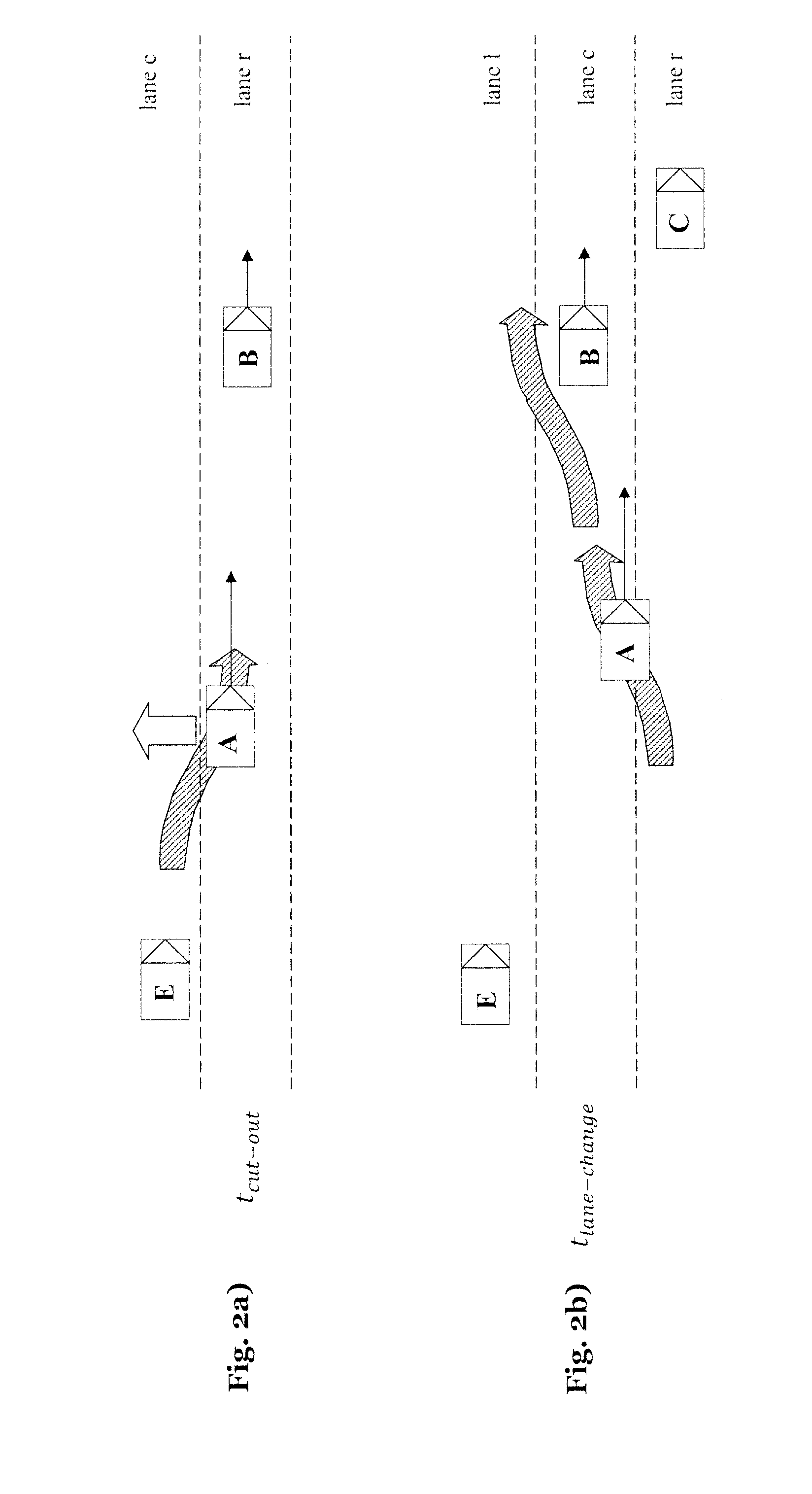
According to EP 2 562 060 A1, this will result in decelaration of the host vehicle, because in such a situation it is likely that the target vehicle will cut in to overtake the slower predecessor vehicle.
Firstly, it could of course well be that the target vehicle in fact was on the neighboring lane for a long time and therefore will in fact overtake the predecessor vehicle.
As a result of this previous behavior, the target vehicle now quickly approaches its predecessor, but a probability that this target object again cuts in before it was overtaken by the host vehicle is rather low.
The known context-based prediction therefore would deliver a wrong result.
The quality of prediction of such systems is therefore quite limited.

Method used


Image

  • Method and system for predicting movement behavior of a target traffic object
  • Method and system for predicting movement behavior of a target traffic object
  • Method and system for predicting movement behavior of a target traffic object

Examples


Embodiment Construction

:

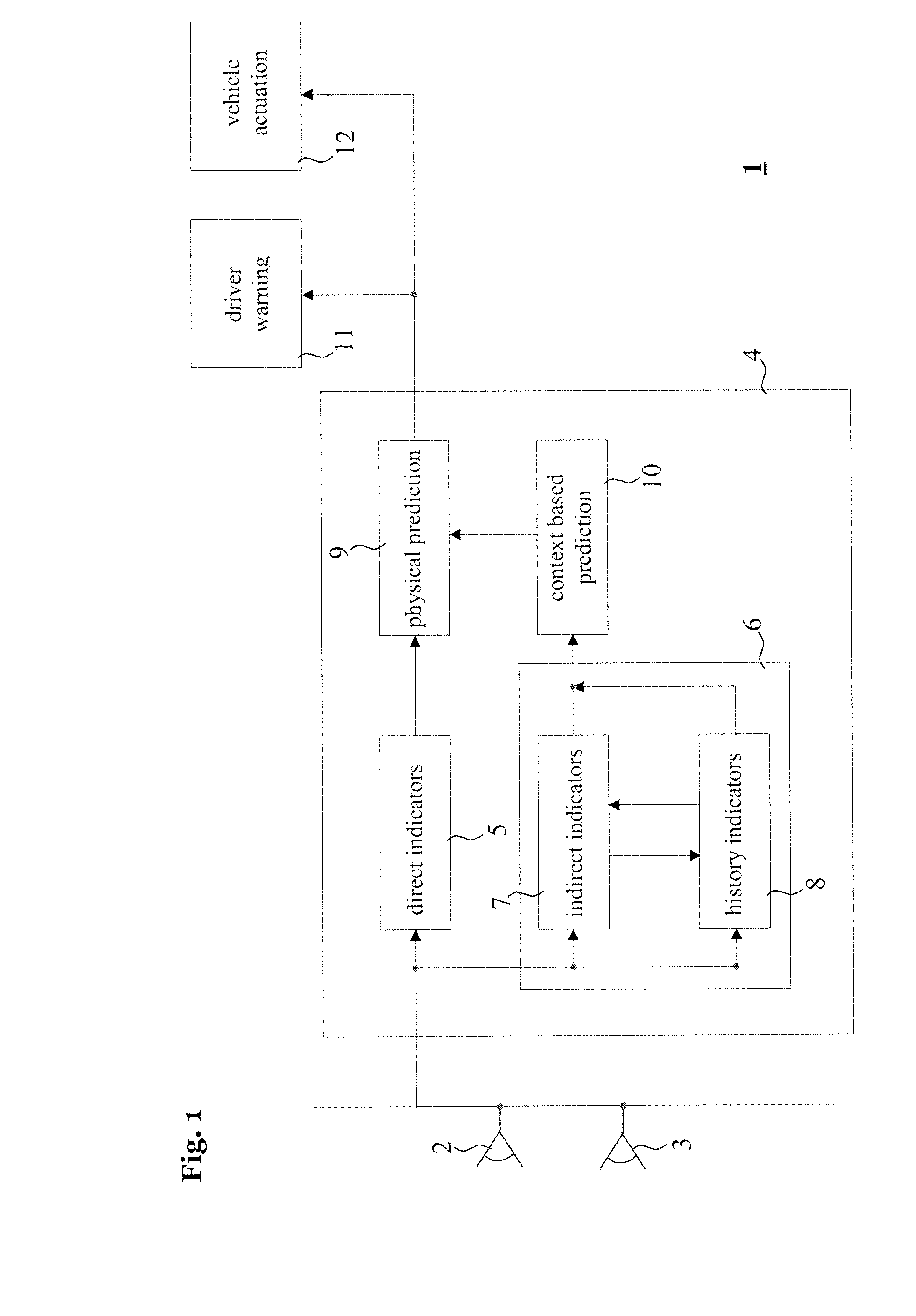
[0075]The inventive system and method is now described in view of the figures.

[0076]The method according to the invention assumes to be performed on / by the host-vehicle or a respective computing system on board of the host-vehicle being equipped with one or more sensors.

[0077]The computing system relates to a system for performing the necessary computing or calculation operations. This system may be specially constructed for this purpose, or it may comprise at least a general-purpose computer selectively activated or reconfigured by a computer program stored in the computer. The computing system can also consist of a network of (different) processors.

[0078]Such a computer program and also data required for its execution may be stored in a computer readable storage medium, such as, but is not limited to, any type of disk including floppy disks, optical disks, CD-ROMs, magnetic-optical disks, read-only memories (ROMs), random access memories (RAMs), EPROMs, EEPROMs, magnetic or optic...


PUM


Abstract

A method for computationally predicting future movement behavior of a target object and program includes producing sensor data by at least one sensor physically sensing the environment of a host vehicle, and computing a plurality of movement behavior alternatives of the target object sensed by the sensors. The computing includes predicting movement behaviors of the target object applying context based prediction using at least one indirect indicator and / or indicator combinations derived from senor data. In the context based prediction, a probability that the target object will execute a movement behavior is estimated. A future position of the target object is estimated and a signal representing the estimated future position is outputted. At least one history indicator for a movement behavior alternative is generated for a current point in time using at least one indicator of an indirect indicator at a point in the past.

Description

BACKGROUND[0001]1. Field[0002]The present invention relates to the field of automated, computerized driver assistance in air, land or sea vehicles, where a sensor of a host vehicle physically senses the environment of the host vehicle, and a computing unit, supplied with an output signal of the sensor, computes a signal which assists in the guidance of the host vehicle when supplied to optical or acoustical indication means and / or when being supplied to an actuator or a controller unit for controlling such actuator of the vehicle. The actuator of the vehicle might be a safety device (airbag, . . . ) or an actuator influencing the movement of the vehicle (flaps, brakes, accelerator, steering, . . . ).[0003]2. Description of the Related Art[0004]Driver assistance systems such as “Adaptive Cruise Control” (ACC) systems (e.g. described in ISO-Norm 15622:2010) increase driver comfort and safety. They are especially used for carrying out longitudinal control of a host vehicle, for example...

Claims


Application Information

Patent Timeline
Patent Type & Authority Applications(United States)
IPC IPC(8): B60W30/14
CPCB60W30/14B60W2750/30B60W2550/30B60W2550/10B60W50/0097B60W30/0956B60W30/16B60W30/18163B60W40/04B60W30/09B60W2554/80B60W2754/10B60W2554/00B60W2556/20B60W2556/10B60W2554/802B60W60/00274
Inventor SCHMUDDERICH, JENS
Owner HONDA RES INST EUROPE
Learn More