

White glass
a technology of white glass and glass, applied in the field of white glass, can solve the problems of increasing the number of steps and cost, the leakage of light from a light-emitting element, and the impairment of the visual beauty of the device, so as to improve the wavelength dependence, excellent designability, and excellent designability in appearan
- Summary
- Abstract
- Description
- Claims
- Application Information
AI Technical Summary
Benefits of technology
Problems solved by technology
Method used
Image

Examples
example 1
[0150]A 15 g batch prepared according to the composition presented in Table 1 was put in a platinum crucible, and melted for 20 minutes at 1,600° C. After the temperature of the furnace was reduced to 1,390° C., the batch was held for 68 minutes at a temperature equal to less than its phase separation starting temperature, and then it was taken out of the furnace and left standing for cooling. The phase separation starting temperature of the glass thus obtained was 1,500° C. Thereafter, the glass was kept at 670° C. for one hour, then annealed to room temperature at a rate of 1° C. / min, followed by subjecting to polishing. Thus, a plate glass was obtained. The dispersed phase of the thus obtained plate glass was an alkali-rich phase.
[0151]The obtained glass contained SO3 because Glauber's salt was added to the batch for the purpose of clarification. The amount of Glauber's salt added was adjusted so that 100 parts by weight of the glass, exclusive of SO3, contained SO3 in a proporti...
example 2
[0152]A 15 g batch prepared according to the composition presented in Table 1 was put in a platinum crucible, and melted for 20 minutes at 1,600° C. After the temperature of the furnace was reduced to 1,420° C., the batch was held for 67 minutes at a temperature equal to less than its phase separation starting temperature, and then it was taken out of the furnace and left standing for cooling. The phase separation starting temperature of the glass thus obtained was 1,500° C. Thereafter, the glass was kept at 670° C. for one hour, then annealed to room temperature at a rate of 1° C. / min, followed by subjecting to polishing. Thus a plate glass was obtained. The dispersed phase of the thus obtained plate glass was an alkali-rich phase.
example 3
[0153]A 15 g batch prepared according to the comopsition presented in Table 1 was put in a platinum crucible, and melted for 20 minutes at 1,600° C. After the temperature of the furnace was reduced to 1,390° C., the batch was held for 68 minutes at a temperature equal to or less than its phase separation starting temperature, and then it was taken out of the furnace and left standing for cooling. The phase separation starting temperature of the glass thus obtained was 1,500° C. Thereafter, the glass was kept at 670° C. for one hour, then annealed to room temperature at a rate of 1° C. / min, followed by subjecting to polishing. Thus, a plate glass was obtained. The dispersed phase of the thus obtained plate glass was an alkali-rich phase.
PUM
| Property | Measurement | Unit |
|---|---|---|
| thickness | aaaaa | aaaaa |
| wavelength range | aaaaa | aaaaa |
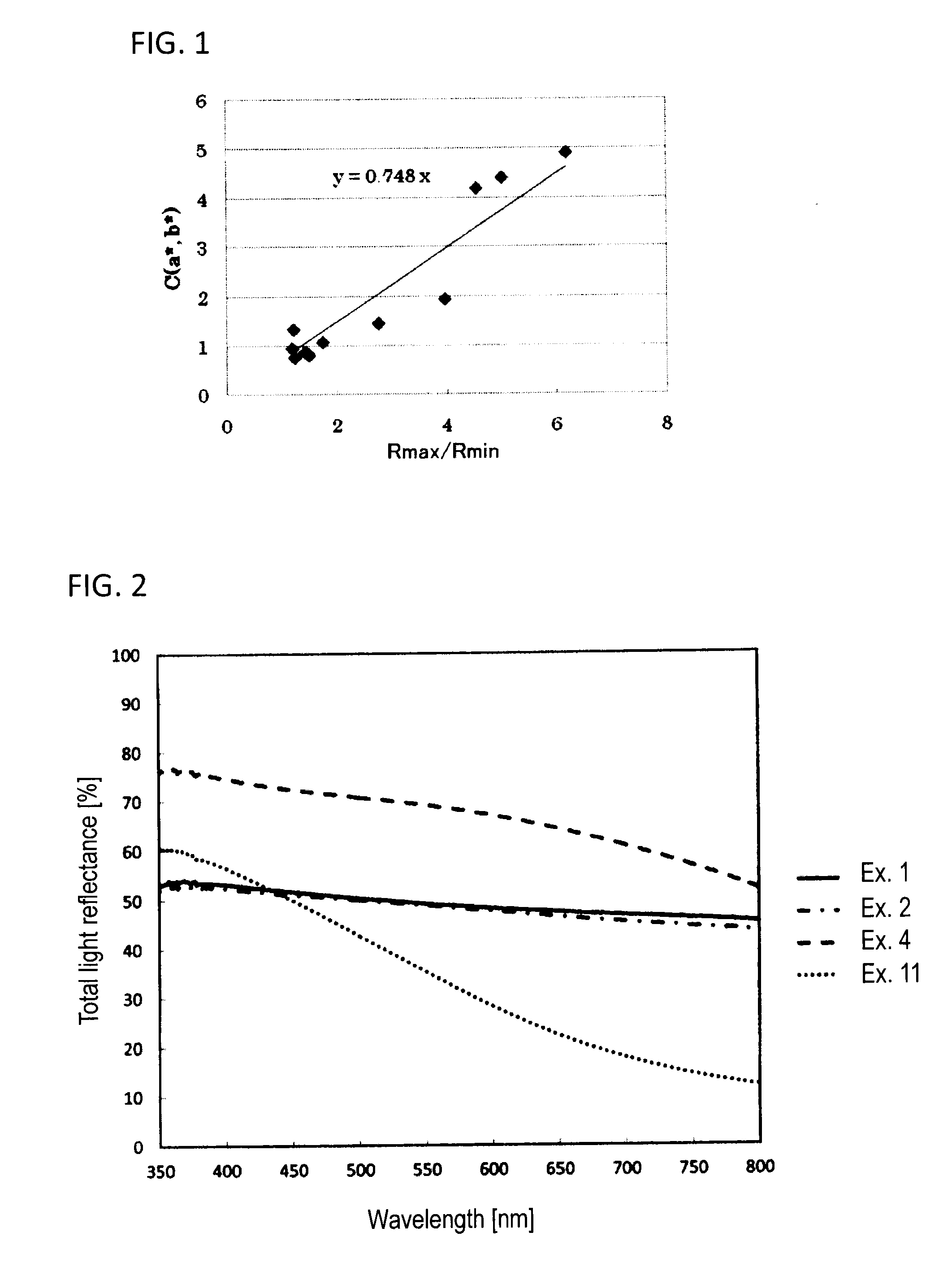
| total light reflectance | aaaaa | aaaaa |
Abstract
Description
Claims
Application Information