

Flexible heat shield with silicone elastomer and a topcoat for inflatable safety devices
a technology of inflatable safety devices and silicone elastomers, which is applied in the direction of applications, pedestrian/occupant safety arrangements, instruments, etc., can solve the problems of inflators that are difficult to sew through and/or package, excessive stiffness or non-flexibility, and can burn through the bags of inflatable devices
- Summary
- Abstract
- Description
- Claims
- Application Information
AI Technical Summary
Benefits of technology
Problems solved by technology
Method used
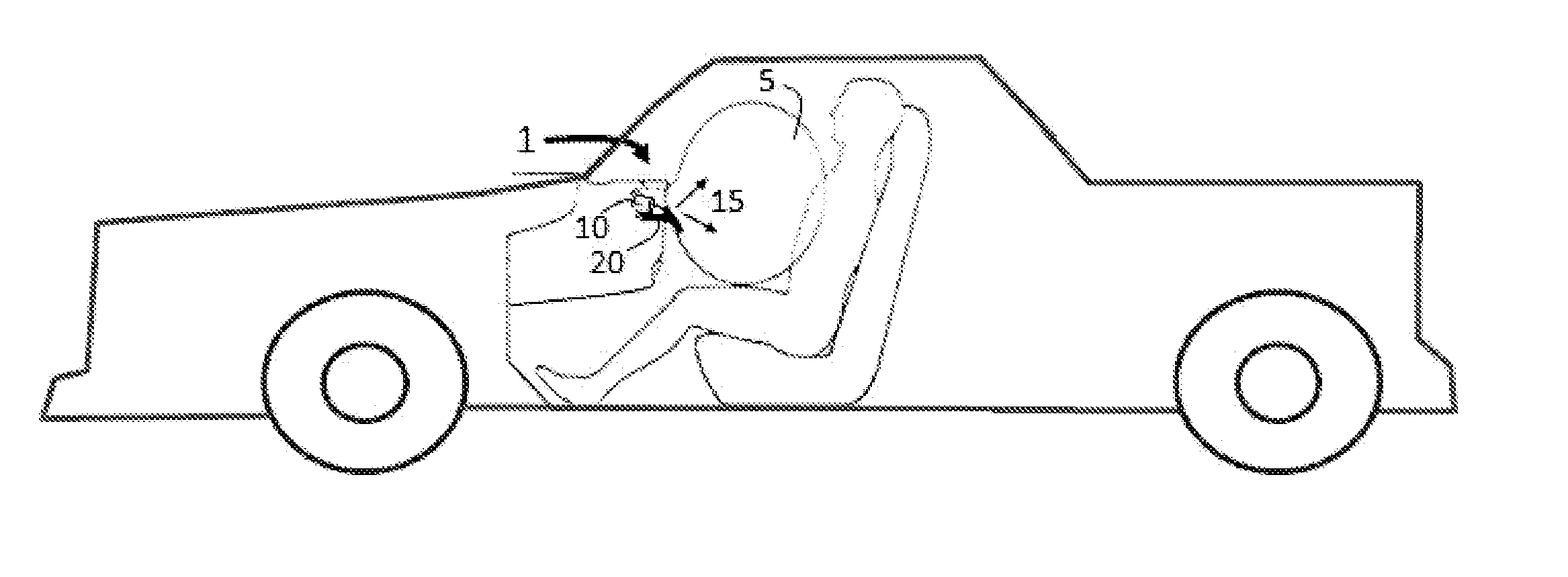
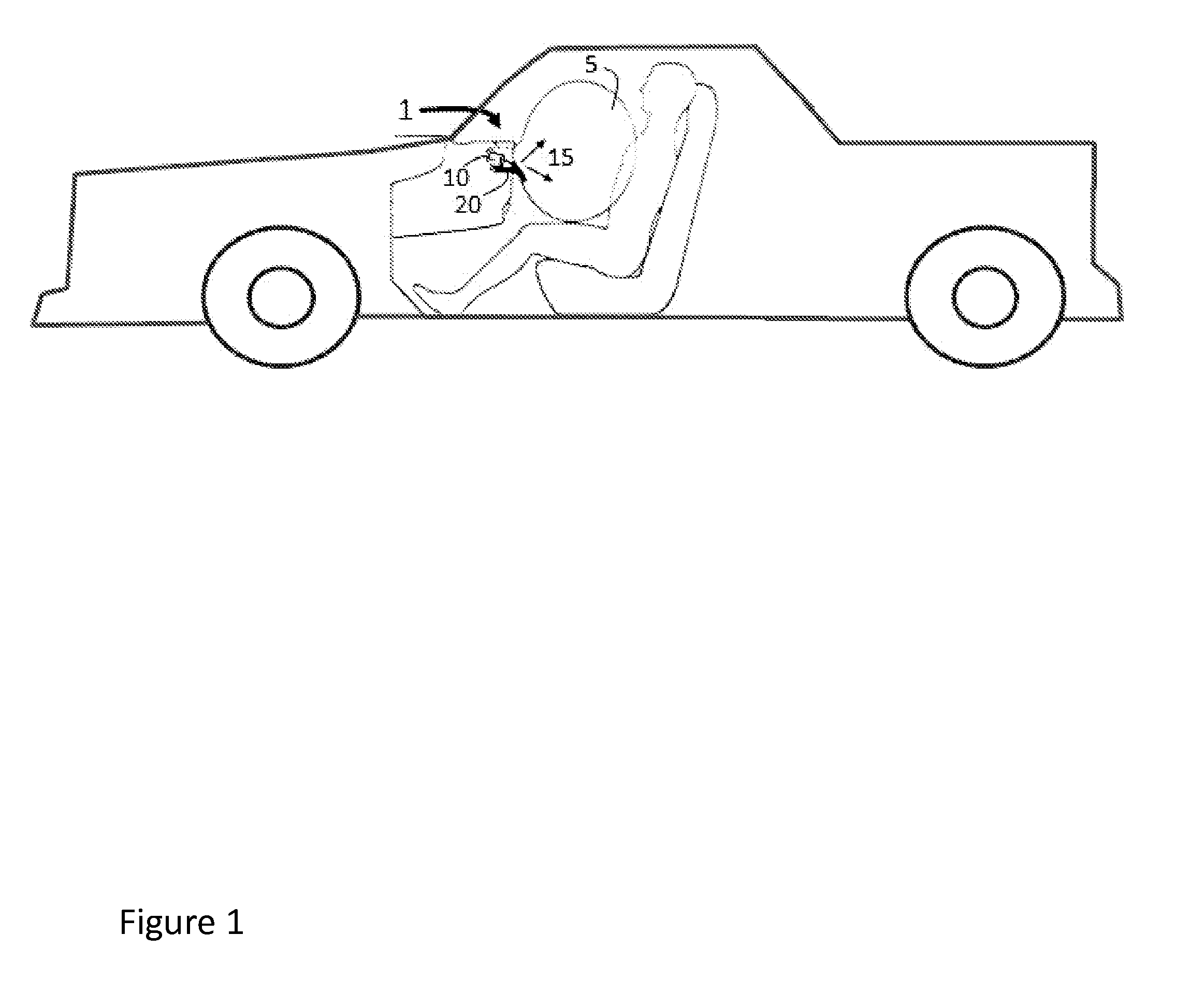
Image

Examples
example 1
Thermal Resistance of a Composite Sheet with Thermal Barrier Layer
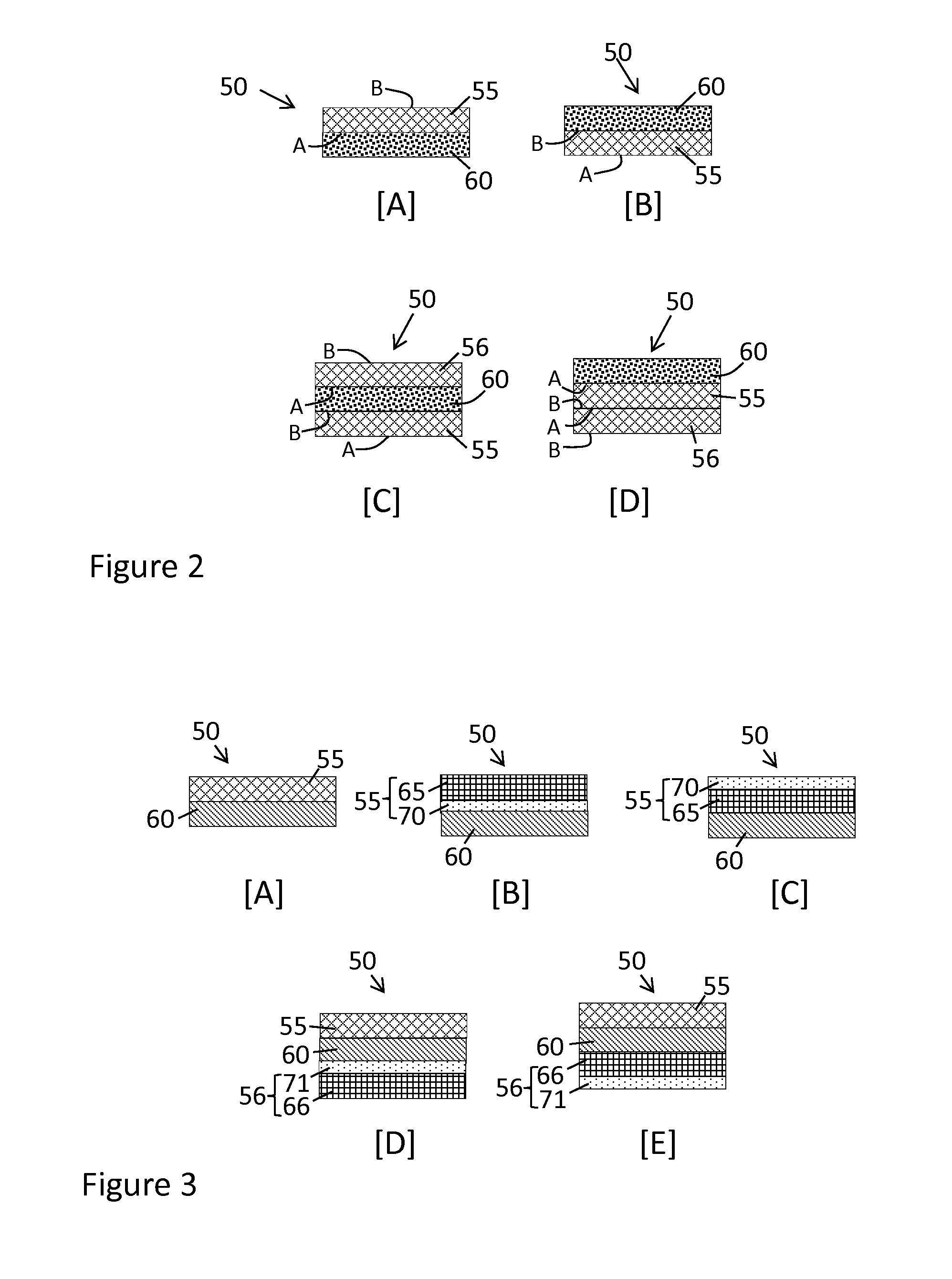
[0076]A composite sheet is prepared and tested using the hot rod test in accordance with the Configurations, A and B, as shown in FIGS. 4A and 4B, respectively. The composite sheet in this example comprises a fabric layer that includes a 700 dtex nylon 6,6 open weave fabric material. The fabric layer does not include any silicone treatment applied to the fabric material. A two-part liquid silicone rubber (LSR) layer (Silastic® 591, Dow Corning Corporation, Midland, Mich.) is applied to the surface of the fabric layer and cured. A two-part liquid silicone rubber topcoat is then applied to the surface of the silicone elastomer and cured to form the barrier layer. The overall amount of silicone elastomer and topcoat used as the barrier layer on the fabric layer is 297 g / m2. The composite sheet is tested in both Configuration A and Configuration B. In Configuration A, the surface that makes initial contact with the hot ro...
example 2
Thermal Resistance of Another Composite Sheet with Thermal Barrier Layer
[0077]A composite sheet is prepared and tested using the hot rod test in accordance with the Configuration C and Configuration D, as described in FIGS. 4C and 4D, respectively. The composite sheet in this example comprises a fabric layer that includes a 470 dtex nylon 6,6 fabric material and a silicone treatment in the amount of 30 g / m2. High consistency rubber (HCR) (52 durometer, 430% elongation, SO33C, Dow Corning Corporation, Midland, Mich.) is applied to the surface of the fabric layer and cured. A two-part liquid silicone rubber topcoat is then applied to the surface of the HCR elastomer layer and cured to form the barrier layer. The overall amount of HCR and topcoat used as the barrier layer applied to the fabric layer is 585 g / m2. The composite sheet is tested in both Configuration C and Configuration D. In Configuration C, the surface that makes initial contact with the hot rod during the performance of...
PUM
| Property | Measurement | Unit |
|---|---|---|
| Temperature | aaaaa | aaaaa |
| Time | aaaaa | aaaaa |
| Time | aaaaa | aaaaa |
Abstract
Description
Claims
Application Information