

Testing rig
- Summary
- Abstract
- Description
- Claims
- Application Information
AI Technical Summary
Benefits of technology
Problems solved by technology
Method used
Image

Examples
Embodiment Construction
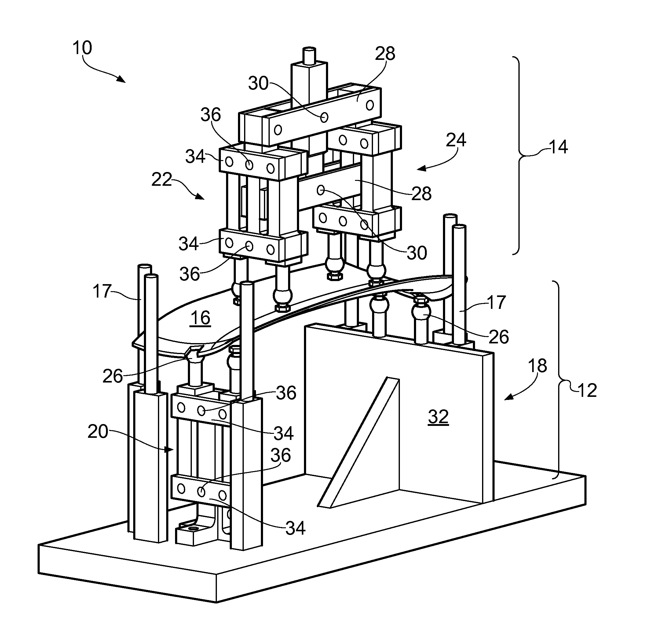
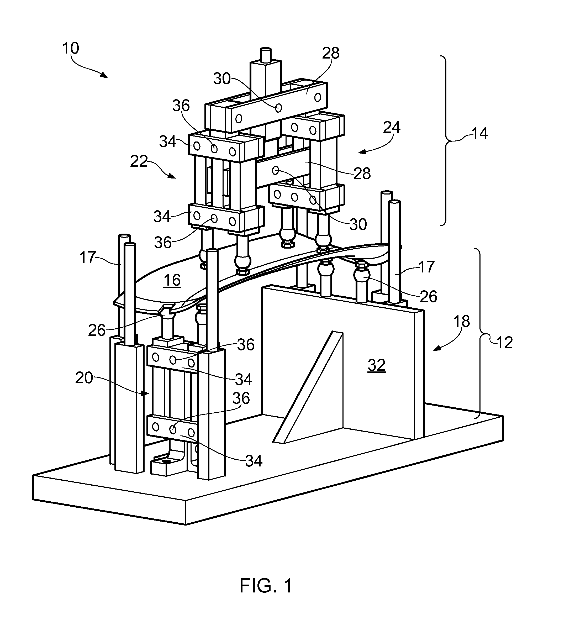
[0027]With reference to FIG. 1, a rig for testing an aerofoil component in four-point bending is generally indicated at 10 and has a direction of application of load which is in the vertical direction of the drawing.
[0028]The rig has lower (first) fixture 12 and an upper (second) fixture 14. Lower fixture is securely and rigidly mountable to an immovable base, while the upper fixture 14 is movable up and down in the vertical direction, for example by a hydraulic or electrically driven jack or cross-head of a universal testing machine. A gas turbine engine aerofoil component 16, such as a fan blade, is located between the lower and upper fixtures, supported on the lower fixture.
[0029]The component extends substantially horizontally with its opposing aerofoil surfaces facing upwards and downwards. Guide posts 17 serve to locate component in the correct position on the lower fixture.
[0030]The component 16 has a complex shape, which also deforms in a complex and uneven manner under load...
PUM
 Abstract
Description
Claims
Application Information