Container-holding tray

a container and tray technology, applied in the field of container holding tray, can solve the problems of serious impact on the liquid medicine and the specimen, and achieve the effect of simple method and stable holding of the container

Active Publication Date: 2015-10-01
DAIKYO SEIKO LTD
View PDF26 Cites 8 Cited by
  • Summary
  • Abstract
  • Description
  • Claims
  • Application Information

AI Technical Summary

Benefits of technology

[0018]The container-holding tray according to the present invention is capable of preventing water from flowing to the inside of the container and simultaneously surely sterilizing the inside of the container during high pressure steam sterilization. In addition, the container-holding tray makes it possible to stably hold the container by a simple method.BRIEF EXPLANATION OF THE DRAWINGS
[0019]FIG. 1 is a perspective view schematically showing an embodiment of a container-holding tray according to the present invention;
[0020]FIG. 2 is a side view schematically showing a state of the container-holding tray shown in FIG. 1, when seen from the side thereof;
[0021]FIG. 3 is a plan view schematically showing a state of the container-holding tray shown in FIG. 1, when seen from the upper part thereof;
[0022]FIG. 4 is an enlarged plan view schematically enlarging and showing a part of the container-holding tray shown in FIG. 3, the part being indicated by references A and B;
[0023]FIG. 5 is an enlarged sectional view schematically enlarging and showing a state of the container-holding tray shown in FIG. 4, when being cut along the line C-C;

Problems solved by technology

A medical container such as vial, syringe barrel is a container into which a liquid medicine, a specimen collected from the human body or the like is injected, thus if a microorganism is adhered to the surface of the container or the like, it may have a serious impact on the liquid medicine and the specimen.

Method used


Image

  • Container-holding tray
  • Container-holding tray
  • Container-holding tray

Examples


example 1

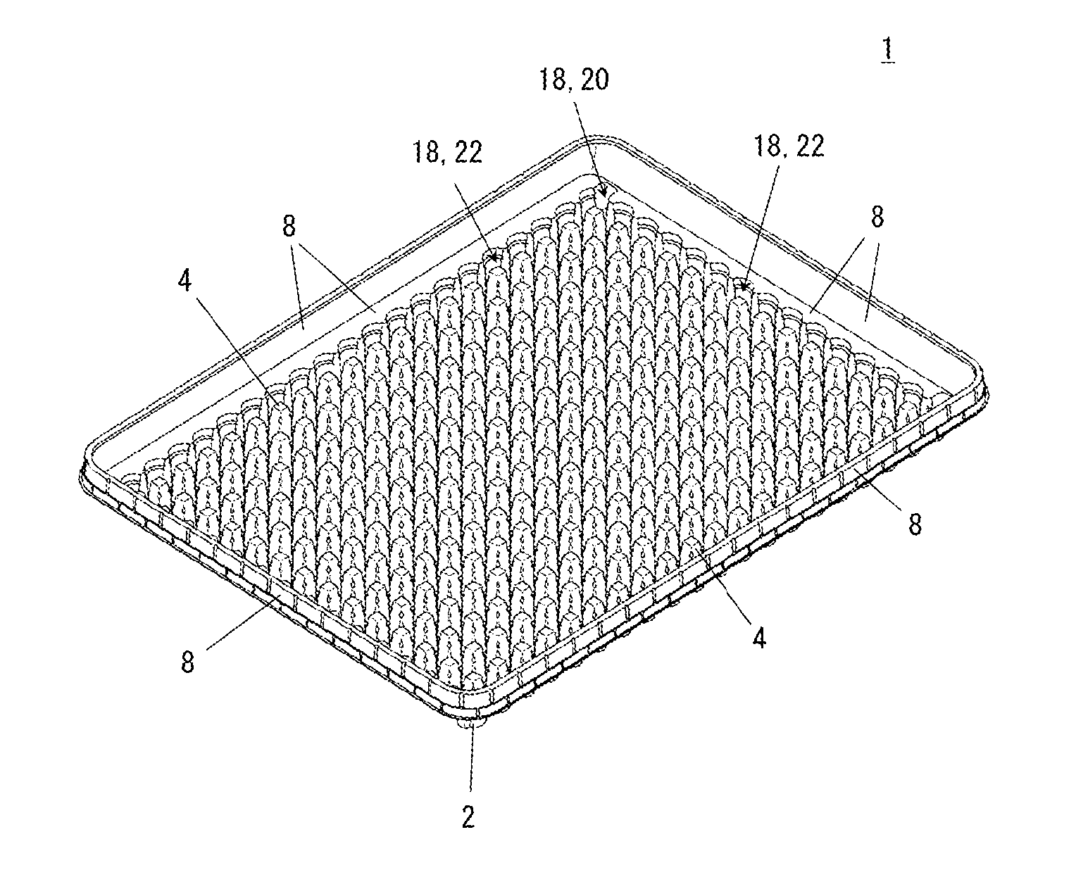
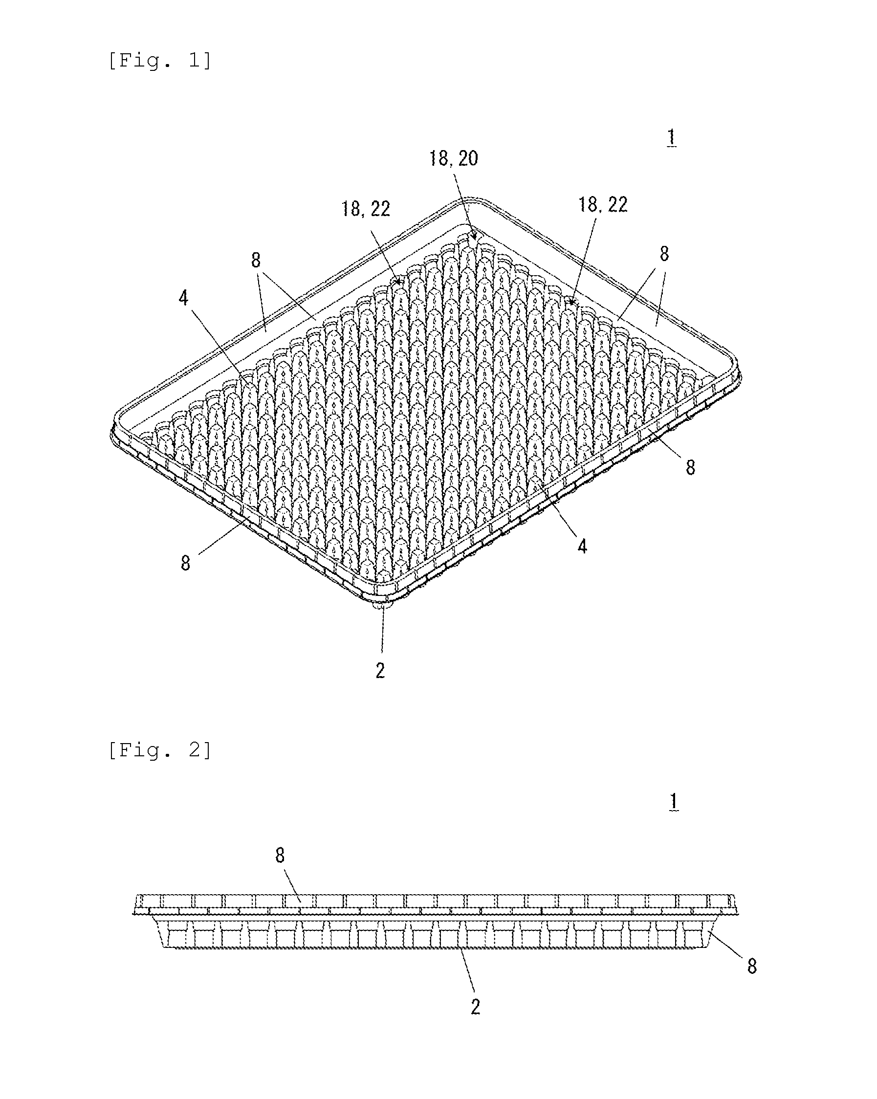
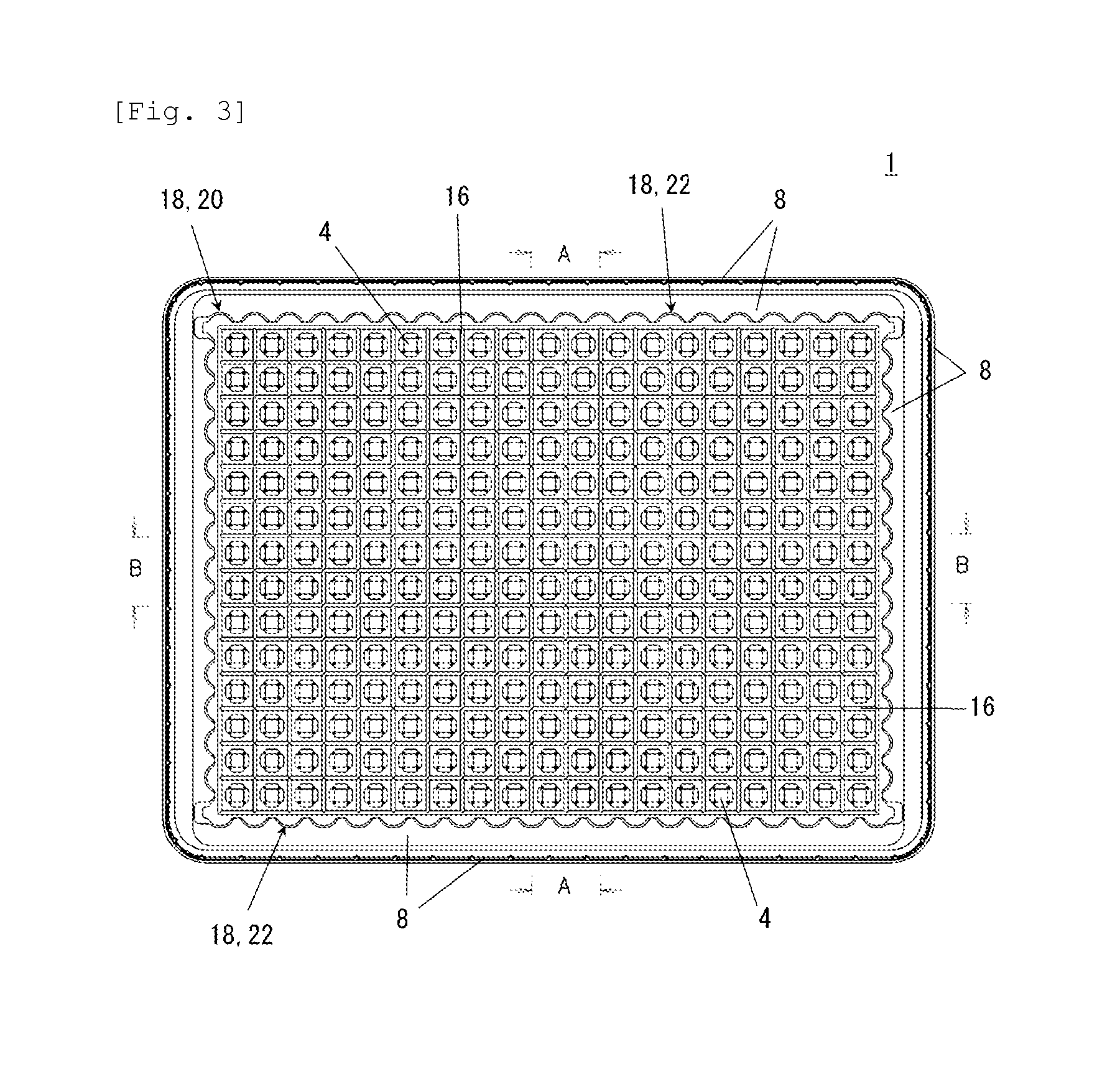
[0073]Container-holding trays that differ from the container-holding tray 1 shown in FIG. 1 to FIG. 7 only in the number of the container holding convex part 4 were manufactured. Since a basic structure thereof is the same as that of the container-holding tray 1, hereinafter an explanation will be carried out referring to FIG. 1 to FIG. 7. The container-holding tray 1 was configured to have an approximately rectangular shape in a plan view from the upper side and to have a size as a whole that is 400 mm long, 300 mm wide and 45 mm high. The container-holding tray 1 was manufactured by using a polypropylene resin as a raw material and by the vacuum molding. The container-holding tray 1 was configured to have a thickness of 1.0 mm.

[0074]As the medical container that is an object to be held, the medical container 50 (vial) as shown in FIG. 8 was conceived. The medical container 50 is a vial configured such that the volume is approximately 5 ml, the whole height is 38 mm, the outer diam...

example 2

[0080]The container-holding tray 101 shown in FIG. 9 to FIG. 11 was manufactured. The container-holding tray 101 was configured to have the same shape in a plan view from the upper side, the size as a whole, the raw material, the thickness, and the object to be held as the container-holding tray of Example 1. However, it was manufactured by the injection molding.

[0081]On the bottom surface part 102 of the tray, 140 pieces of the container holding convex parts 104 were arranged. Each of the container holding convex parts 104 has an approximately different diameter cylindrical shape. More specifically, the different diameter cylindrical shape has a basic shape that is constituted of one cylindrical shape on the bottom surface side and another cylindrical shape on the top surface side, the one cylindrical shape being configured such that the outer diameter is 13.7 mm Ø and the height is 14.5 mm, and the another cylindrical shape being configured such that the outer diameter is 12.0 mm ...


PUM


Abstract

The present invention relates to a container-holding tray 1 for holding a plurality of bottomed cylindrical medical containers 50 side by side. The container-holding tray 1 includes the bottom surface part 2 and the container holding convex parts 4 formed on the bottom surface part 2 and configured to hold the medical containers 50, wherein each of the container holding convex parts 4 has a tapered shape that is thin on the upper end side thereof, the plurality of the container holding convex parts 4 are configured to a lattice arrangement on the bottom surface part 2, and simultaneously four of the container holding convex parts 4 are integrated, thereby a container housing part 6 corresponding to one of the medical containers is formed, and the medical containers 50 are configured to be brought into contact with any point from the upper end to the lower end of the four convex parts 4 so as to be held.

Description

TECHNICAL FIELD[0001]The present invention relates to a container-holding tray for holding a plurality of bottomed cylindrical medical containers such as vial, syringe barrel side by side.BACKGROUND ART[0002]A medical container such as vial, syringe barrel is a container into which a liquid medicine, a specimen collected from the human body or the like is injected, thus if a microorganism is adhered to the surface of the container or the like, it may have a serious impact on the liquid medicine and the specimen. Accordingly, the medical container is usually used after sterilization is carried out.[0003]As a method of the sterilization, a high-pressure steam sterilization is widely adopted, the method being configured such that the medical container of a sterilization object is sterilized by being exposed to a high temperature and high pressure steam atmosphere for a predetermined time (121° C., 20 minutes or the like). In addition, in the high pressure steam sterilization, for the p...

Claims


Application Information

Patent Timeline
Patent Type & Authority Applications(United States)
IPC IPC(8): A61J1/16B65D1/36
CPCB65D1/36A61J1/16A61M5/002A61M5/008F04C2270/0421
Inventor TSUKIJI, DAISUKE
Owner DAIKYO SEIKO LTD
Why Eureka
Try Eureka