
Firefighting or rescue apparatus including side access ladder

a technology for firefighting or rescue apparatus and side access ladders, which is applied in the direction of transportation and packaging, transportation items, items transportation vehicles, etc., can solve the problems of potentially dangerous delays, impaired ingress and egress of users to the ladder, and unusable access ladders, etc., to facilitate enhanced access to an aerial ladder, facilitate enhanced access, and facilitate quick and easy access

Active Publication Date: 2015-10-01
HME
View PDF13 Cites 26 Cited by
  • Summary
  • Abstract
  • Description
  • Claims
  • Application Information

AI Technical Summary

Benefits of technology

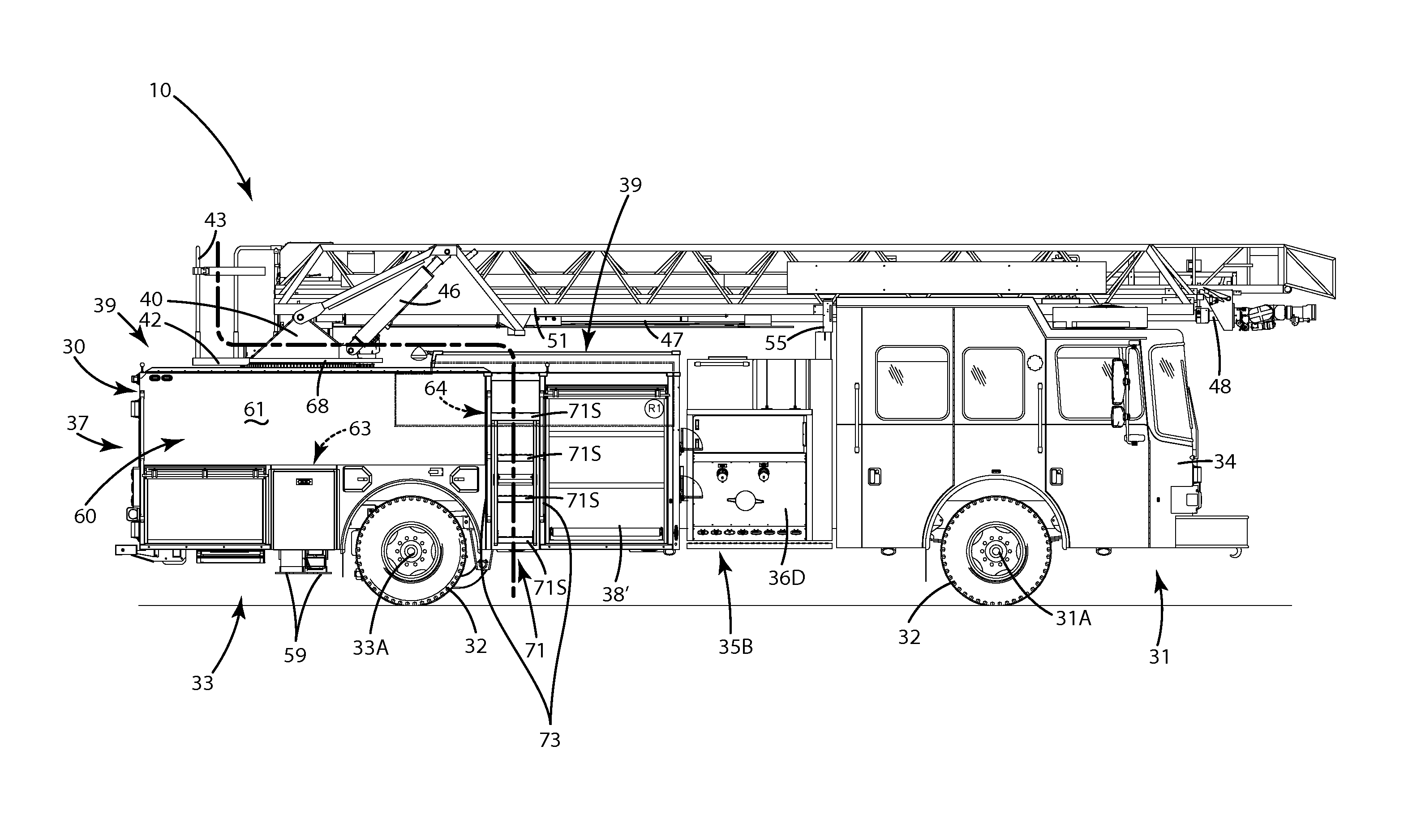
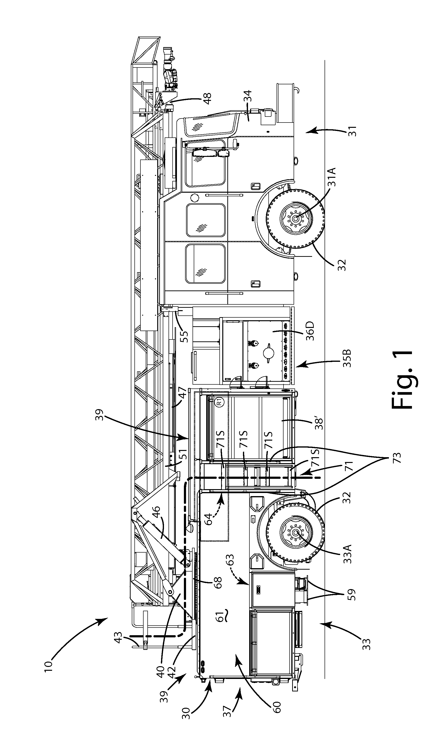
The invention provides a firefighting or rescue apparatus with an aerial ladder and a side stack hose bed that can be accessed even when the aerial ladder is in use. The side access ladder and hose bed cover can form a path from the ground to the aerial ladder and provide access to the hose bed. The hose bed can also have a floor and serve as a walking platform or a container for the fire hose. The invention allows for enhanced access to the aerial ladder and other firefighting or rescue equipment even when certain access ladders are obstructed.

Problems solved by technology

These access ladders typically are the only ladders rearward of the cab (other than the aerial ladder), so when one of the access ladders is blocked by the aerial ladder extending in a direction over or near the access ladder, that access ladder is rendered unusable.
In turn, the ingress and egress of users to the ladder is impaired, and use is limited to one access ladder.
Where time is of the essence in a rescue operation, this access impairment can cause potentially dangerous delays.
This can further impair access to the ladder platform and upper deck of the truck.

Method used


Image

  • Firefighting or rescue apparatus including side access ladder
  • Firefighting or rescue apparatus including side access ladder
  • Firefighting or rescue apparatus including side access ladder

Examples


Embodiment Construction

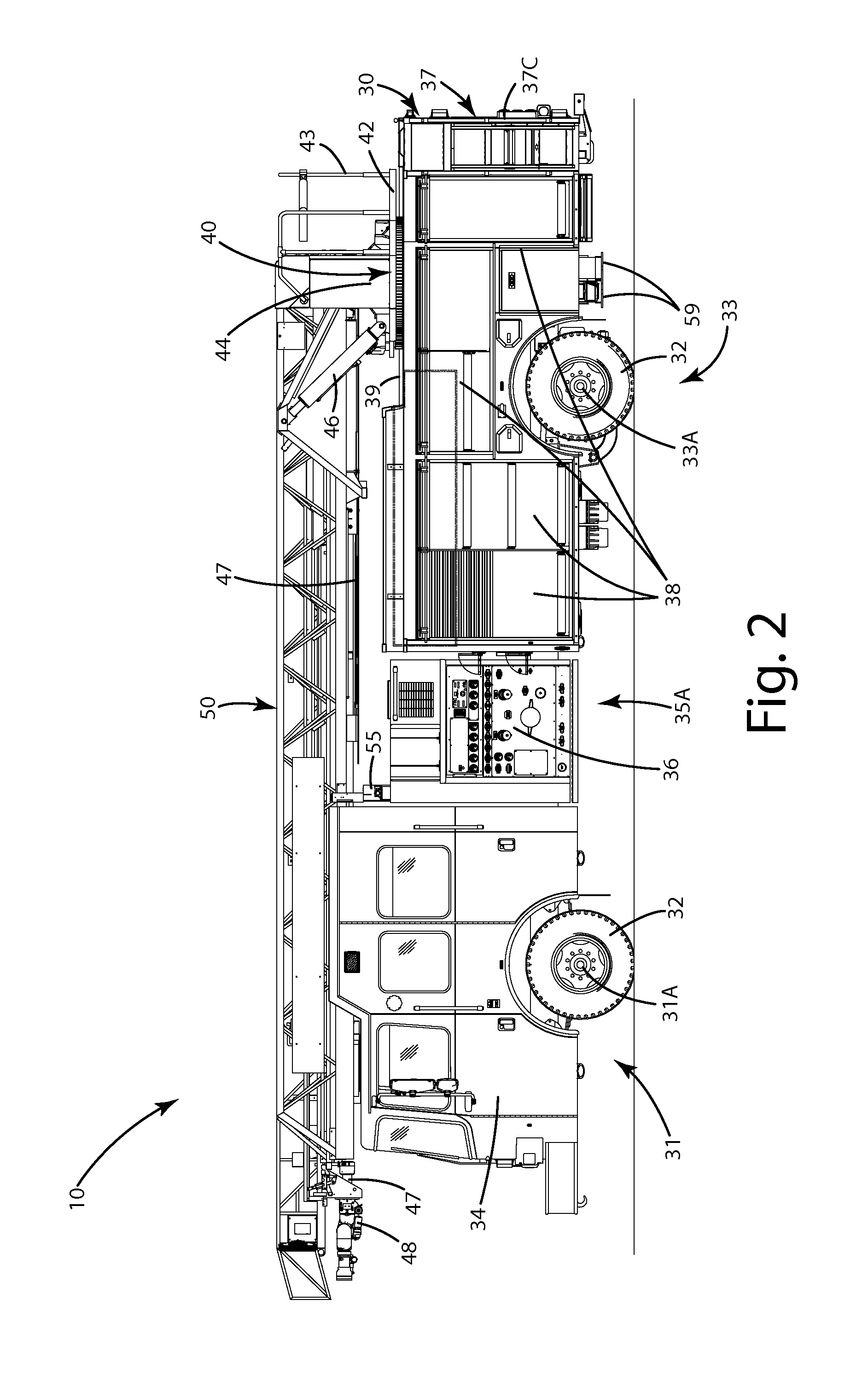
[0023]A current embodiment of an aerial firefighting apparatus is illustrated in FIGS. 1-10 and generally designated 10. As shown there, the aerial firefighting apparatus is in the form of an aerial ladder fire truck. Although referred to as an aerial firefighting apparatus, as used herein, that term can also include a variety of emergency vehicles, rescue vehicles and other modes of transportation such as aerial ladder trailers or other equipment. Generally, the aerial ladder apparatus, referred to herein as a fire truck, can be a self-propelled vehicle including a ladder 50. The ladder can be mounted on a frame 30 of the fire truck via a rotatable turntable 40.

[0024]The frame 30 of the fire truck 10 can be mounted to a chassis which can be further mounted to multiple wheels 32. The wheels can be attached to conventional front and rear axles, which are further attached to the chassis of the truck. The fire truck can be mobilized via an internal combustion engine which drives the wh...


PUM


Abstract

A firefighting or rescue apparatus includes an aerial ladder, a side stack hose bed and a side access ladder that provides access to the aerial ladder when the aerial ladder obstructs another access ladder. The side stack hose bed is mounted to a frame in a rearward portion of the apparatus. A first side access ladder is mounted to a first side of the frame forward of the side stack hose bed and optionally forward of the rear axle. Another second side access ladder is mounted to a second side of the frame. A movable side stack hose bed cover extends over the hose bed, and can include a rigid plate extending from the first side access ladder toward the aerial ladder. The first side access ladder and hose bed cover cooperatively form a path from a ground location toward the aerial ladder to facilitate access to the aerial ladder.

Description

BACKGROUND OF THE INVENTION[0001]The present invention relates to a firefighting apparatus, such as a fire truck, a trailer or other vehicles, and more particularly to a firefighting apparatus with an aerial ladder and one or more side access ladders.[0002]There are a variety of fire trucks and rescue vehicles that include aerial ladders to assist in the fighting of fires. These aerial ladders usually are mounted on a frame or chassis of a fire truck. The ladder can be raised from a generally horizontal position to an angled position so that the ladder extends upwardly from the frame. The ladder can be extended and retracted to achieve varying heights for rescue operations and / or for the application of firefighting fluids.[0003]Generally, aerial ladder trucks are used to fight fires from elevated positions or to rescue victims trapped in burning buildings. Many times, an aerial ladder truck is dispatched to an emergency location such as the location of a traffic accident, a boating ...

Claims


Application Information

Patent Timeline
IPC IPC(8): A62C27/00
CPCA62C27/00E06C5/02E06C5/04A62C31/24
Inventor LENZ, JR., KENNETH C.LONGHURST, KEVIN J.
Owner HME
Learn More