Liquid ejecting head, liquid ejecting apparatus, and method of manufacturing liquid ejecting head

a technology of liquid ejection and liquid ejection, which is applied in the direction of metal-working equipment, printing, writing implements, etc., can solve the problems of deformation and warping, and achieve the effect of suppressing deformation of the holder and improving the quality of liquid ejection

Active Publication Date: 2015-10-01
SEIKO EPSON CORP
View PDF1 Cites 5 Cited by
  • Summary
  • Abstract
  • Description
  • Claims
  • Application Information

AI Technical Summary

Benefits of technology

[0010]An advantage of some aspects of the invention is to provide a liquid ejecting head and liquid ejecting apparatus in which size increases are suppressed and in which the ejection quality of the liquid is improved by suppressing deformation of the holder member that holds the head main bodies, and a method or manufacturing the liquid ejecting head.Aspect 1
[0012]In this case, it is possible to correct warping in a direction perpendicular to the liquid ejecting surface of the holder member by providing the first correction plate in the holder member. In other words, even if warping occurs during manufacturing or during heating of the holder member, it is possible to maintain a state in which warping the holder member is corrected by bonding the first correction plate to the holder member in a state in which the warping of the holder member is corrected. In so doing, the liquid ejecting surface of the head main bodies held by the holder member is made flush, the landing position precision of the liquid on the recording medium is improved, and a liquid ejecting head with improved ejection quality is obtained. The cover member accommodates both the circuit substrate and the first correction plate. Compared to a case where only the circuit substrate is accommodated by the cover member, it is possible to reduce the size of the liquid ejecting head. Since the circuit substrate is erected perpendicular with respect to the liquid ejecting surface, it is possible for the region occupied by the circuit substrate to be reduced in the surface direction of the liquid ejecting surface. In so doing, it is possible for the size of the liquid ejecting head to be reduced in the surface direction of the liquid ejecting surface.Aspect 2
[0013]In the liquid ejecting head according to Aspect 1, it is preferable that the first correction plate include a correction main body portion that extends over the connection portion in a direction perpendicular to the liquid ejecting surface, and an opening portion provided in the correction main body portion and through which the wiring substrate passes. In so doing, it is possible to strengthen the correction of the holder member.Aspect 3
[0016]In the liquid ejecting head according to Aspects 1 to 4, it is preferable that a second correction plate that is a planar shaped second correction plate parallel to the liquid ejecting surface, is more rigid than the holder member, and is adhered to the holder be provided, in which the second correction plate has a size that covers all of the liquid ejecting surface of the head main body on the surface parallel to the liquid ejecting surface. Thereby, since the second correction plate is adhered to the holder member that holds all of the head main bodies, it is possible to more reliably correct distortion or torsion during manufacturing or the like. It is possible for the rigidity of the liquid ejecting head to be further improved by the second correction plate.Aspect 6
[0025]In this case, a liquid ejecting head is provided in which size increases are suppressed and the liquid ejection quality is improved by suppressing deformation of the holder member that holds the head main bodies.

Problems solved by technology

However, there is concern of deformation such as warping arising during manufacturing or heating of the flow channel member formed with a resin material.
When a flow channel in which warping arises in this way is used, the liquid ejecting surfaces of the head main bodies held in the flow channel member are not gathered in the same plane and there is concern of shifting of the landing positions of ink on the recording medium such as a recording sheet.
Such a problem is present for not only an ink jet recording head that discharges ink but also for a liquid ejecting head and liquid ejecting apparatus that eject a liquid other than ink and a method of manufacturing a liquid ejecting head.

Method used


Image

  • Liquid ejecting head, liquid ejecting apparatus, and method of manufacturing liquid ejecting head
  • Liquid ejecting head, liquid ejecting apparatus, and method of manufacturing liquid ejecting head
  • Liquid ejecting head, liquid ejecting apparatus, and method of manufacturing liquid ejecting head

Examples


embodiment 1

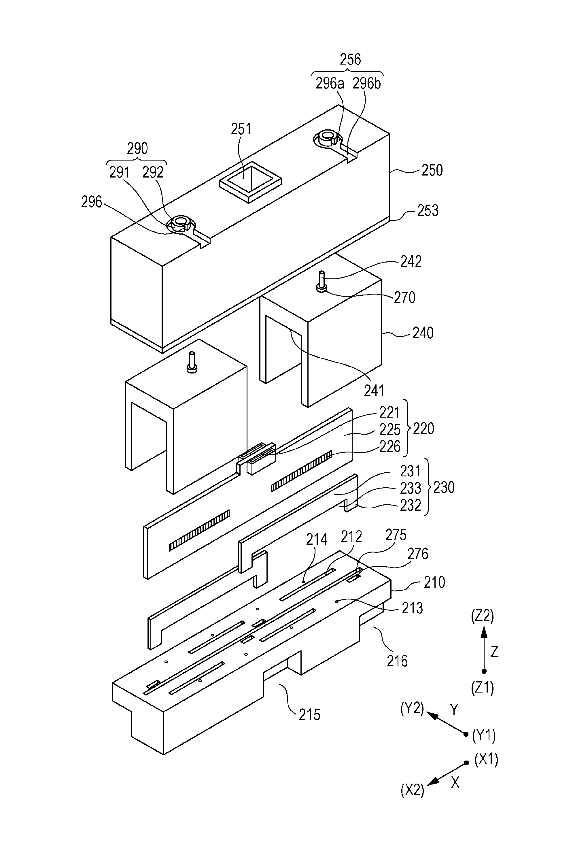
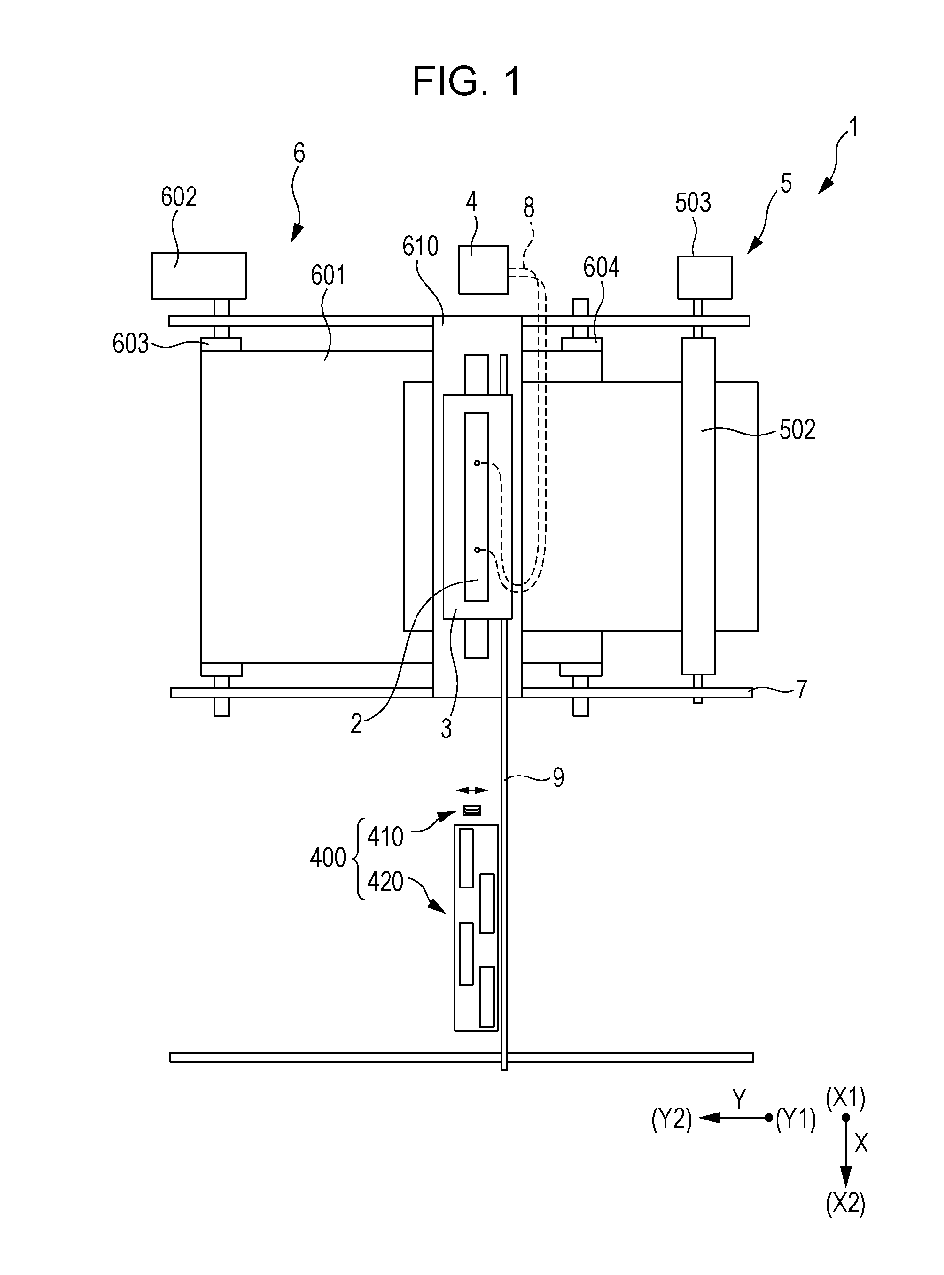
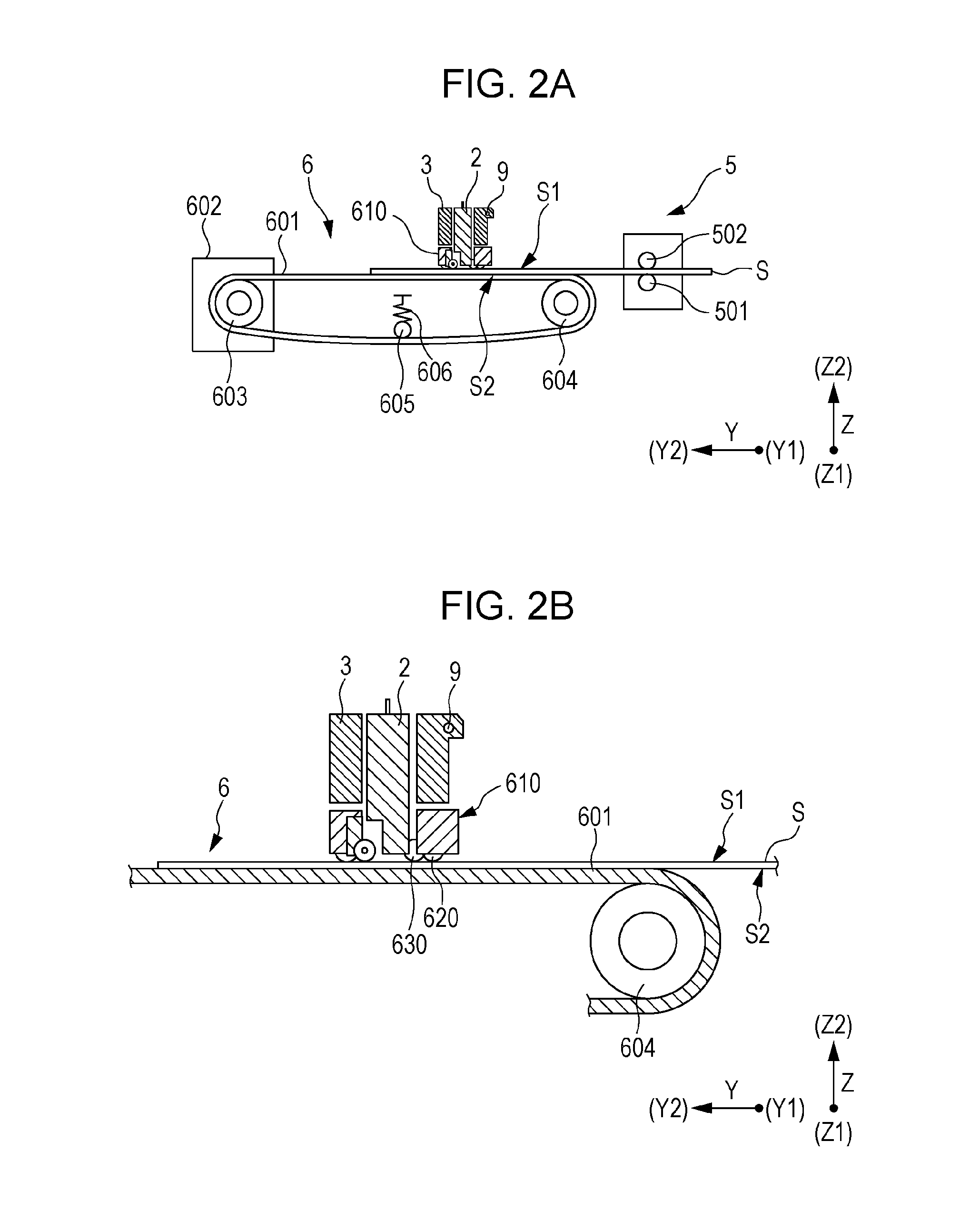
[0056]Detailed description will be provided based in the embodiments of the invention. The ink jet recording head is an example of a liquid ejecting head and is also simply referred to as a recording head. The ink jet recording apparatus is an example of a liquid ejecting apparatus. FIG. 1 is a plan view schematically showing an ink jet recording apparatus according to Embodiment 1 and FIGS. 2A and 2B are a side view and an enlarged view of the ink jet recording apparatus.

[0057]The ink jet recording apparatus 1 is a so-called line-type ink jet recording apparatus 1 that performs printing by transporting only the recording sheet S that is a recording medium.

[0058]The transport direction of the recording sheet S is referred to as the second direction Y and the direction orthogonal to the second direction Y in the in plane direction of the landing plane S1 of the recording sheet S on which the ink lands is referred to as the first direction X. A direction orthogonal to both the first d...

embodiment 2

[0302]The second correction plate 280 of the recording head 2 according to the Embodiment 1 is provided with an opening 281 in which the protrusion 217 provided with the first connection flow channel 213 and the second connection flow channel 214 is inserted. Although the opening 281 is does not configure the flow channel through which ink flows, there is no limitation to such a form, and the second correction plate 280 preferably configures the ink flow channel.

[0303]FIG. 29 is an enlarged cross-sectional view of the main portions of the head main body, second correction plate, and holder member 210 according to the Embodiment 2. The same like element as Embodiment 1 are given the like reference symbols and overlapping description will not be made.

[0304]The second correction plate 280A of the recording head 2A according to the embodiment configures the ink flow channel. Specifically, a through hole 283 that penetrates along the third direction Z, and that configures a portion of th...


PUM

PropertyMeasurementUnit
thicknessaaaaaaaaaa
liquid ejectingaaaaaaaaaa
widthaaaaaaaaaa

Abstract

A liquid ejecting head comprising: a head body that ejects liquid droplets from a liquid ejecting surface; a wiring substrate electrically connected to the head body; a holder member to which the head bodies are fixed, and that includes a flow channel to the head bodies, and a wiring through hole through which the wiring substrate passes; a circuit substrate that includes a connection portion electrically connected to the wiring substrate, and a substrate that arranges the connection portion on both surfaces thereof and stands in a direction intersecting the liquid ejecting surface; a set of a first correction plate facing each other with respect to each of both surfaces of the substrate of the circuit substrate for correcting the holder member; and a cover member that accommodates the circuit substrate fixed to the holder member and the first correction plate.

Description

CROSS REFERENCES TO RELATED APPLICATIONS[0001]This application claims priority to Japanese Patent Application No. 2014-072629 filed on Mar. 31, 2014. The entire disclosure of Japanese Patent Application No. 2014-072629 is hereby incorporated herein by reference.BACKGROUND[0002]1. Technical Field[0003]The present invention relates to a liquid ejecting head, a liquid ejecting apparatus, and a method of manufacturing a liquid ejecting head, and in particular relates to an ink jet recording head that ejects ink as a liquid, an ink jet recording apparatus, and a method of manufacturing an ink jet recording head.[0004]2. Related Art[0005]The liquid ejecting apparatus represented by an ink jet recording apparatus, such as an ink jet printer or plotter, includes a liquid ejecting head able to eject a liquid such as ink stored in a cartridge, tank or the like. Such a liquid ejecting head includes a plurality of head main bodies that eject a liquid and a flow channel member (corresponds to a ...

Claims


Application Information

Patent Timeline
Patent Type & Authority Applications(United States)
IPC IPC(8): B41J2/14B41J2/16
CPCB41J2/1433B41J2002/14491B41J2/1623B41J2/162B41J2/14233B41J2/155B41J2002/14241B41J2002/14419B41J2202/20Y10T29/49401B41J2/14209
Inventor KOMATSU, YUKOKINOSHITA, RYOTATAKINO, FUMIYA
Owner SEIKO EPSON CORP
Why Eureka
Try Eureka