Apparatus for pile-driving or drilling

a technology of piled-driving or drilling apparatus, which is applied in the direction of rotary drilling, foundation engineering, percussion drilling, etc., can solve the problems of power loss, large block, high construction cost, and loss of control block power, so as to avoid the loss of pumping power and improve efficiency.

Active Publication Date: 2015-10-01
ABI ANLAGENTECHN BAUMASCHEN INDBEBEDARF
View PDF1 Cites 3 Cited by
  • Summary
  • Abstract
  • Description
  • Claims
  • Application Information

AI Technical Summary

Benefits of technology

[0009]With the invention, an apparatus for pile-driving or drilling, particularly a foundation machine having a hydraulic drilling or vibration drive, is created, in which the hydraulic power lost as the result of the flow resistance in the control block is reduced. Because the drive is additionally connected directly with the pump, by way of a second feed line, and directly with the tank, by way of a second return line, the control block is disposed hydraulically parallel to the actual working lines that lead directly from the pump to the work device as the main consumer and from the work device to the tank. The control block is therefore switched as a bypass for the direct connections between pump and working device and between working device and tank. In this way, direct application of hydraulic oil to the work device is made possible.
[0012]In a further embodiment of the invention, the drive is directly connected with the pump by way of a third return line. In this embodiment at least one valve, in each instance, preferably a directional valve, is provided for optional separation of the hydraulic drive with the tank and connection of the hydraulic drive and the pump, in such a manner that a closed circuit between pump and drive can be achieved. Via the valves provided, the suction line in the pump can be optionally connected with the tank or with the return line from the work device. In this way, priming losses of the pump can be avoided.
[0013]Furthermore, the pump can be impacted with an elevated input pressure in this manner. Last but not least, greater efficiency can be achieved by means of a closed hydraulic circuit.

Problems solved by technology

The previously known solutions have the disadvantage that the control block represents a hydraulic resistance for the oil volume stream.
A reduction of this power loss can be achieved by means of using a larger block having a larger cross-section, but this larger block requires a lot of construction space and is furthermore very expensive.
The lost power of the control block is caused by the flow valves used in the control block.
If only one consumer is being operated, for example a vibration pile-driver during pile-driving operation, when a vibrator uses the full power as the sole consumer, the control block does not have any function; it merely serves to pass the oil volume stream through, but does hinder the passage of the oil volume stream as a consequence of the design-related flow resistance.

Method used


Image

  • Apparatus for pile-driving or drilling
  • Apparatus for pile-driving or drilling
  • Apparatus for pile-driving or drilling

Examples


Embodiment Construction

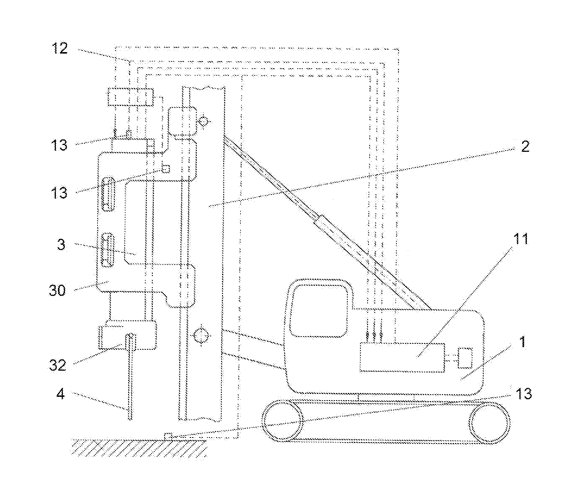
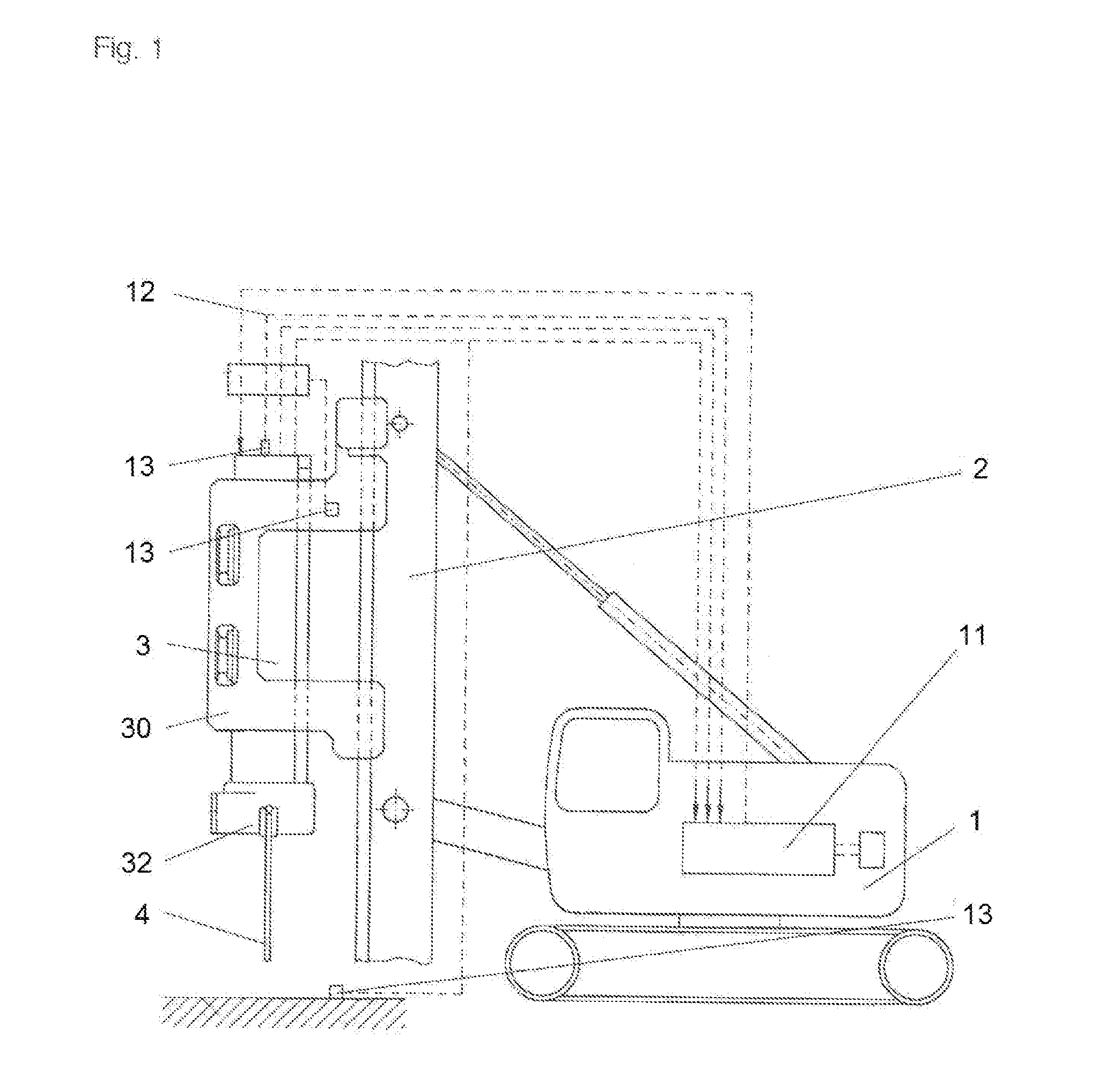
[0022]Referring now in detail to the drawings the apparatus according to the invention will be described using a vibration pile-driver, the essential components of which are shown in FIG. 1. A vibration generator (vibrator) 3 is disposed on a carrier device 1, so as to be vertically displaceable by way of a leader 2. The vibration generator 3 comprises a housing 31 (FIG. 2) that is surrounded by a hood 30. A clamping gripper 32 for holding material 4 to be pile-driven is disposed on the hood 30. The hood 30 serves for guiding the vibration generator 3 and transfers the static force of the leader 2 to the vibration generator 3. The vibration generator 3 generates a vibration, by way of rotating imbalances 3311, 3321, 3331, 3511, 3521, 3531, which vibration is transferred to the material 4 to be pile-driven by way of the clamping gripper 32. Control of the vibration pile-driver takes place by way of a controller apparatus 11 that is connected with different sensors 13 by way of lines ...


PUM


Abstract

An apparatus for pile-driving or drilling, particularly a foundation machine, including at least one hydraulic drilling or vibration drive, which is connected with a control block in an open hydraulic circuit, by way of which drive at least one further consumer can be operated. The drive is connected with a pump by way of a first feed line and with a tank by way of a first return line. The hydraulic drive is additionally connected directly with the pump by way of a second feed line, and directly with the tank by way of a second return line.

Description

CROSS REFERENCE TO RELATED APPLICATIONS[0001]Applicant claims priority under 35 U.S.C. §119 of European Application No. 14163092.1 filed Apr. 1, 2014, the disclosure of which is incorporated by reference.BACKGROUND OF THE INVENTION[0002]1. Field of the Invention[0003]The invention relates to an apparatus for pile-driving or drilling, particularly a foundation machine.[0004]2. Description of the Related Art[0005]Leader-guided vibration pile drivers as well as drilling devices and foundation machines in general are regularly operated hydraulically. In this connection, an open hydraulic circuit is used, because in this way, in contrast to a closed circuit, the operation of different work devices, such as, for example, vibrators, drilling drives, presses, etc., as well as a switch between different consumers such as a work device or a drive of a crawler track drive is made possible. The open hydraulic circuit has a control block or valve block, from which different consumers can be cont...

Claims


Application Information

Patent Timeline
Patent Type & Authority Applications(United States)
IPC IPC(8): E02D7/18E21B1/02E02D7/22E21B7/02E21B3/02
CPCE02D7/18E21B7/022E21B1/02E02D7/22E21B3/02
Inventor HEICHEL, CHRISTIANKLEIBL, ALBRECHT
Owner ABI ANLAGENTECHN BAUMASCHEN INDBEBEDARF
Why Eureka
Try Eureka