Bearing lubricating structure for gas turbine engine

a technology for gas turbine engines and bearings, which is applied in the direction of turbine/propulsion lubrication, hot gas positive displacement engine plants, gas turbine plants, etc., can solve the problems of increasing the weight and cost of the gas turbine engine, the bulky size of the oil pump, and the insufficient lubrication so as to increase the load of the second bearing, increase the amount of oil needed, and prevent the effect of insufficient lubrication

Active Publication Date: 2015-10-01
HONDA MOTOR CO LTD
View PDF1 Cites 9 Cited by
  • Summary
  • Abstract
  • Description
  • Claims
  • Application Information

AI Technical Summary

Benefits of technology

[0012]According to the second aspect, the low-pressure system shaft and the high-pressure system shaft rotate reversely to each other. This increases load of the second bearing so as to increase an amount of oil needed for the second bearing. However, the oil with the sum of the required oil lower limit amount B and the safety surplus oil amount C is supplied to the second bearing which tends to receive an insufficient amount of oil because of its remoteness from the oil supply source. Thereby, insufficient lubrication of the second bearing can be securely prevented.

Problems solved by technology

However, the foregoing conventional gas turbine engine is likely to be unable to supply a sufficient amount of oil to the differential bearing which needs a larger amount of oil because the bearing with which the low-pressure system shaft is supported by the casing is disposed in a supply passage of the oil from the oil jet to the differential bearing so that the bearing consumes the oil.
However, the increase in the capacity of the oil pump raises a problem of: making an oil tank and the oil pump bulky in size; and accordingly increasing weight and cost of the gas turbine engine.

Method used


Image

  • Bearing lubricating structure for gas turbine engine
  • Bearing lubricating structure for gas turbine engine
  • Bearing lubricating structure for gas turbine engine

Examples


Embodiment Construction

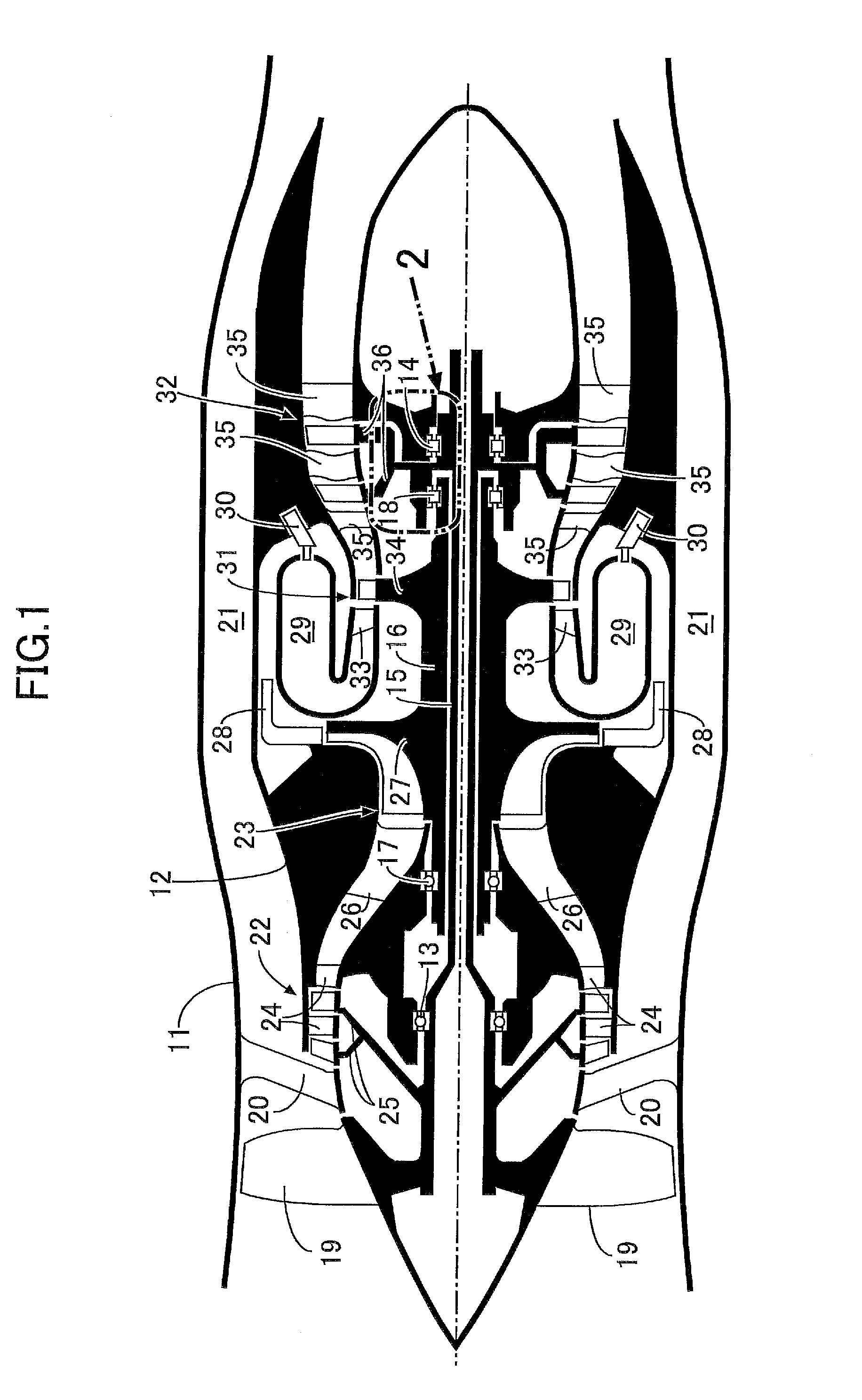
[0020]Descriptions will be hereinbelow provided for an embodiment of the present invention on the basis of FIGS. 1 to 5.

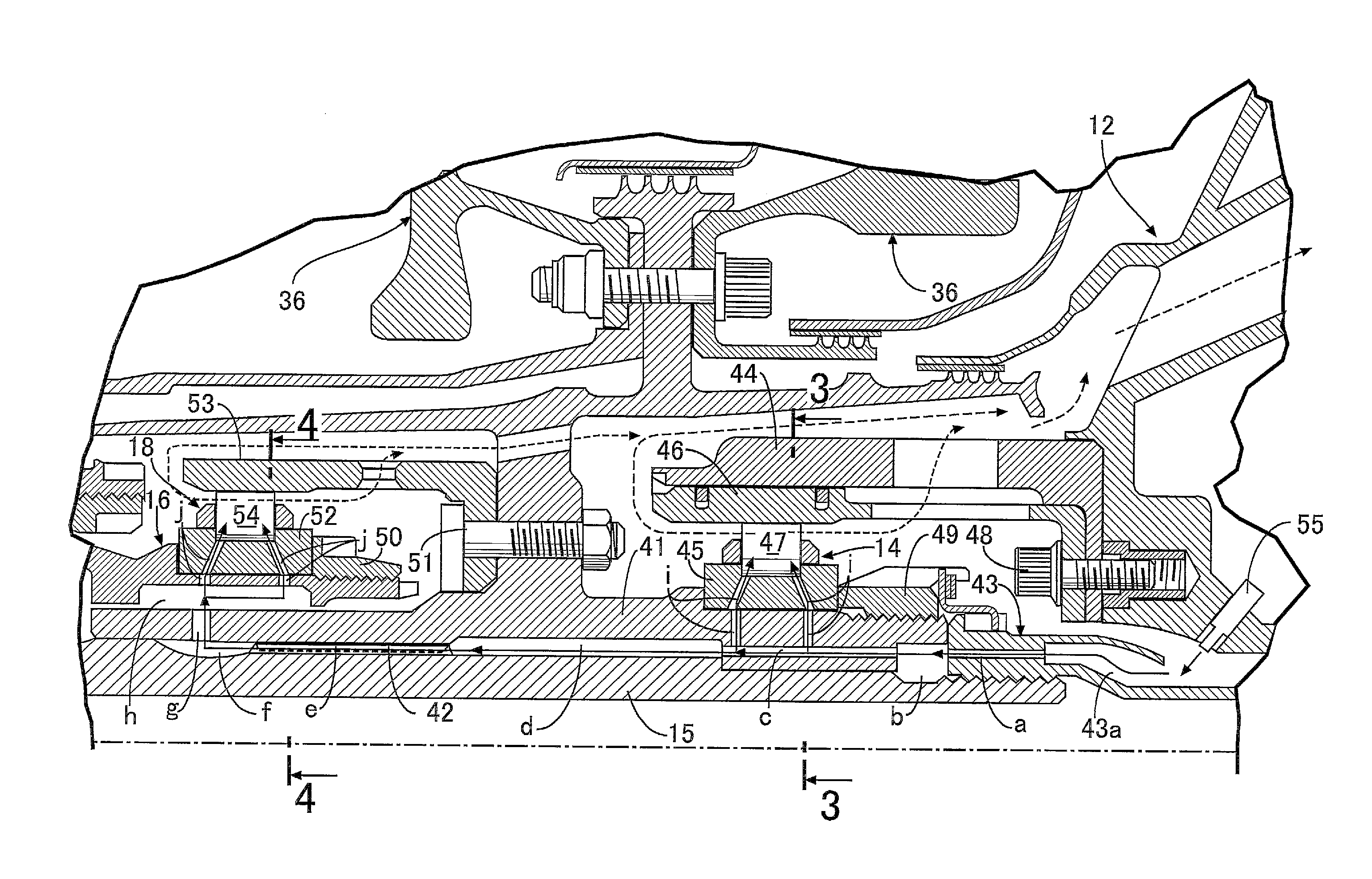
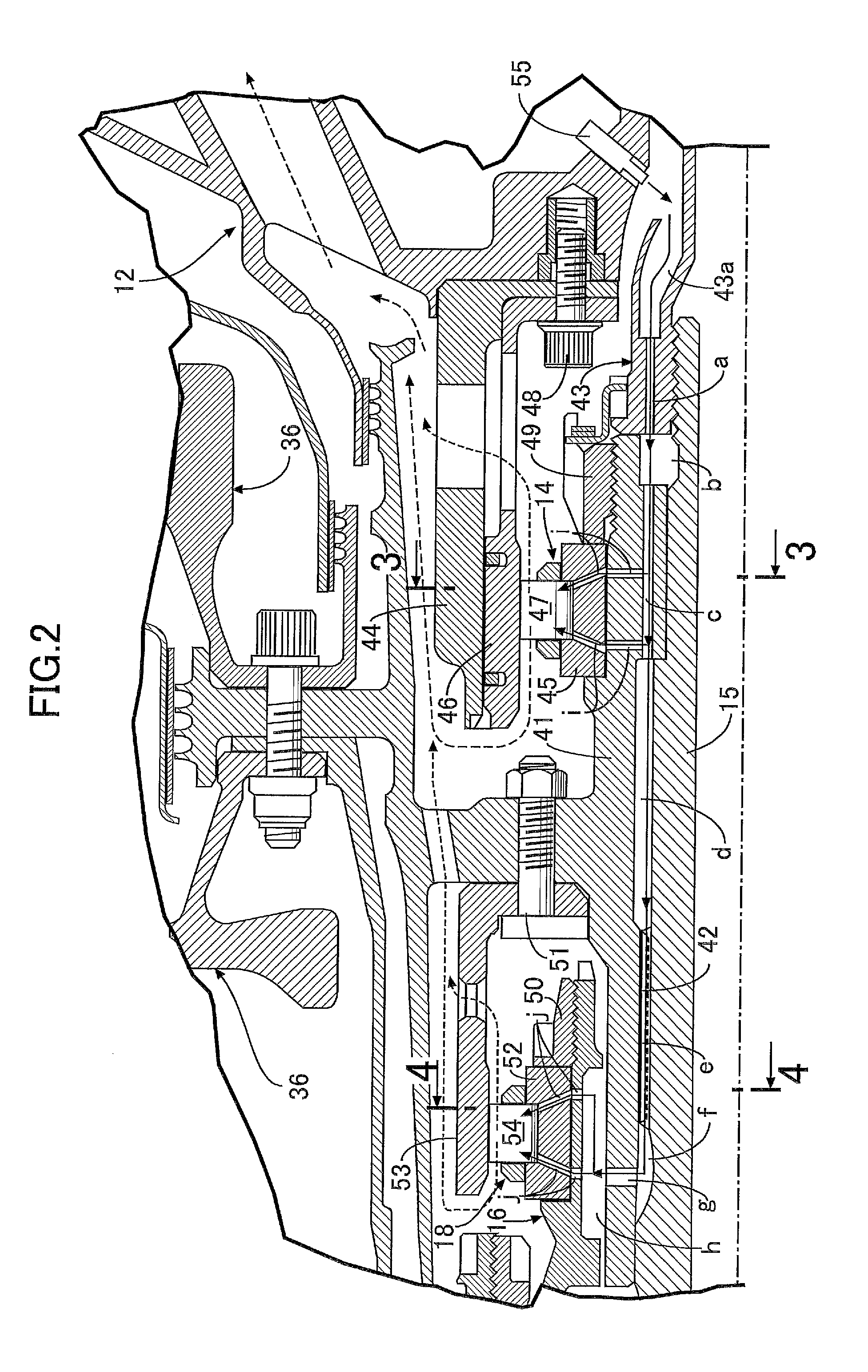
[0021]As shown in FIG. 1, a twin-spool turbofan engine for an aircraft to which the present invention is applied includes an outer casing 11 and an inner casing 12. Front and rear portions of a low-pressure system shaft 15 are rotatably supported by an inside of the inner casing 12 via front and rear first bearings 13, 14, respectively. A tubular high-pressure system shaft 16 is fitted to an outer periphery of an axial-direction intermediate portion of the low-pressure system shaft 15 in a relatively rotatable manner. A front portion of the high-pressure system shaft 16 is rotatably supported by the inner casing 12 via a front second bearing 17, while a rear portion of the high-pressure system shaft 16 is supported by the low-pressure system shaft 15 in a relatively rotatable manner via a rear second bearing 18.

[0022]A front fan 19 having blade ends which face an i...


PUM


Abstract

When A denotes a required oil lower limit amount for one bearing near an oil supply source, and B and C respectively denote a required oil lower limit amount and a safety surplus oil amount for the other bearing away from the source, an amount of oil equal to A+B+C is supplied from the source and a hole diameter and the number of first oil holes are set such that an amount of oil to be supplied to the one bearing is equal to the amount A. Thus, the oil with the amount A can be securely supplied to the one bearing. Also, oil with the sum of the amounts B and C is supplied to the other bearing so that the oil with the amount B can be securely supplied to the other bearing which tends to receive oil insufficiently because of its remoteness from the source.

Description

CROSS REFERENCE TO RELATED APPLICATIONS[0001]The present application claims priority under 35 U.S.C. §119 to Japanese Patent Application No. 2014-67817 filed Mar. 28, 2014 the entire contents of which are hereby incorporated by reference.BACKGROUND OF THE INVENTION[0002]1. Field of the Invention[0003]The present invention relates to a bearing lubricating structure for a gas turbine engine, the engine including a low-pressure system shaft, and a high-pressure system shaft fitted to an outer periphery of the low-pressure system shaft in a relatively rotatable manner, in which the low-pressure system shaft is supported by a casing via a first bearing, the high-pressure system shaft is supported by the low-pressure system shaft via a second bearing, and oil is supplied to the first bearing and the second bearing from an oil supply source.[0004]2. Description of the Related Art[0005]A twin-spool gas turbine engine, in which a high-pressure system shaft is disposed on an outer periphery o...

Claims


Application Information

Patent Timeline
Patent Type & Authority Applications(United States)
IPC IPC(8): F02C7/06F01D25/18
CPCF01D25/18F02C7/06F05D2240/50
Inventor KIMURA, HIDEMI
Owner HONDA MOTOR CO LTD
Why Eureka
Try Eureka