Structure for shaft, male member, and female member

a technology for shafts and members, applied in the direction of yielding couplings, fastening means, rod connections, etc., can solve the problems of operator's abnormal feelings, affecting the durability of shaft structures, and affecting the operation of steering wheels, so as to improve reduce the durability of shaft structures, and maintain constant diameter

Inactive Publication Date: 2015-10-01
NITTA CORP
View PDF10 Cites 17 Cited by
  • Summary
  • Abstract
  • Description
  • Claims
  • Application Information

AI Technical Summary

Benefits of technology

[0016][4] In the shaft structure or the male component as one aspect of [3] above, it is preferable that the male component further comprises: a first main body formed at a front side to have a substantially constant diameter while extending in a direction from a front end to a back end; a second main body formed at a back side to have a substantially constant diameter smaller than a diameter of the first main body while extending in a direction from the front end to the back end; and a first tapered part having a diameter smaller in a tapered manner from the front side toward the back side formed so as to connect the first main body and the second main body, wherein in the initial state where the male component is inserted into the female component, the first gaps are generated between: the elastic member covering the sides of the plurality of male spline parts on the first tapered part; and the elastic-member-facing sides of the plurality of female spline parts.
[0017]According to the construction of [4] above, the male component does not have a tapered form as a whole that is smaller in diameter in a tapered manner from the front side toward the back side, but has a tapered form only in part that connects the first main body and the second main body, and in addition, the second main body extends in a straight manner while having a substantially constant diameter from the front end toward the back end. Therefore, when the male component is rotated, the sides of the plurality of male spline parts press the sides of the plurality of female spline parts through the elastic member so that the resulting stress can be dispersed over the second main body extending in a straight manner. Accordingly, a stress concentrated on a part of the plurality of male or female spline parts (more specifically, the sides of the plurality of male or female spline parts) can be relaxed. Such a concentrated stress is generated by a pressure of the sides of the plurality of male spline parts on the sides of the plurality of female spline parts through the elastic member in a circumstance where the male component is tapered as a whole, for example, which would result in a decrease in the durability of the shaft structure. As a result, the construction of [4] above can improve the durability of the shaft structure in comparison with a conventional one.
[0018][5] In the shaft structure or the male component as one aspect of [4] above, it is preferable that the male component further comprises a second tapered part having a diameter smaller in a tapered manner from the front side toward the back side formed further at the back end of the second main body, wherein in the initial state where the male component is inserted into the female component, the first gaps are generated between: the elastic member covering the sides of the plurality of male spline parts on the second tapered part; and the elastic-member-facing sides of the plurality of female spline parts. The concept of “tapered” here includes the concept of “chamfered.”
[0019]According to the construction of [5] above, if either one of the male and female components arranged coaxially along a central axis deviates from the central axis due to a position gap, the elastic member on both of the first tapered part and the second tapered part abuts on the inner peripheral part of the female component, thereby enabling a concentrated stress to be further relaxed in comparison with the case of only the first tapered part.
[0020][6] In the shaft structure as one aspect of [5] above, it is preferable that a pair of male components, as the male component, are arranged such that the female component in a cylindrical form is interposed between the pair of male components, and a part of one of the pair of male components is inserted into an inlet side of the female component while a part of the other of the pair of male components is inserted into an outlet side of the female component. The term “a part” here implies: the second tapered part; the second main body; and a portion positioned midway on the first tapered part.
[0021]According to the construction of [6] above, an embodiment that the cylindrically formed female component is interposed between the pair of male components, as an example of usage conditions of the shaft structure as a product, can also achieve similar effects to those achieved by the construction of [5] above.

Problems solved by technology

As a result, there has been a problem that an operator, who is handling a steering wheel, suffers from abnormal feelings because a large torque is suddenly transmitted from the telescopic shaft to the steering wheel when an electric motor is energized.
More specifically, there has been a problem that, immediately after the operator starts handling the steering wheel, the force required for the operator to handle the steering wheel decreases drastically, which causes the operator to suffer from abnormal feelings.

Method used


Image

  • Structure for shaft, male member, and female member
  • Structure for shaft, male member, and female member
  • Structure for shaft, male member, and female member

Examples


first embodiment

[0068]Hereinafter, a shaft structure (spline) as well as a male component (male spline shaft) and a female component (female spline shaft), both components making up the shaft structure, in a first embodiment of the present invention will be described with reference to FIGS. 1-6.

[0069](Outlined Structure of Electric Power Steering Device)

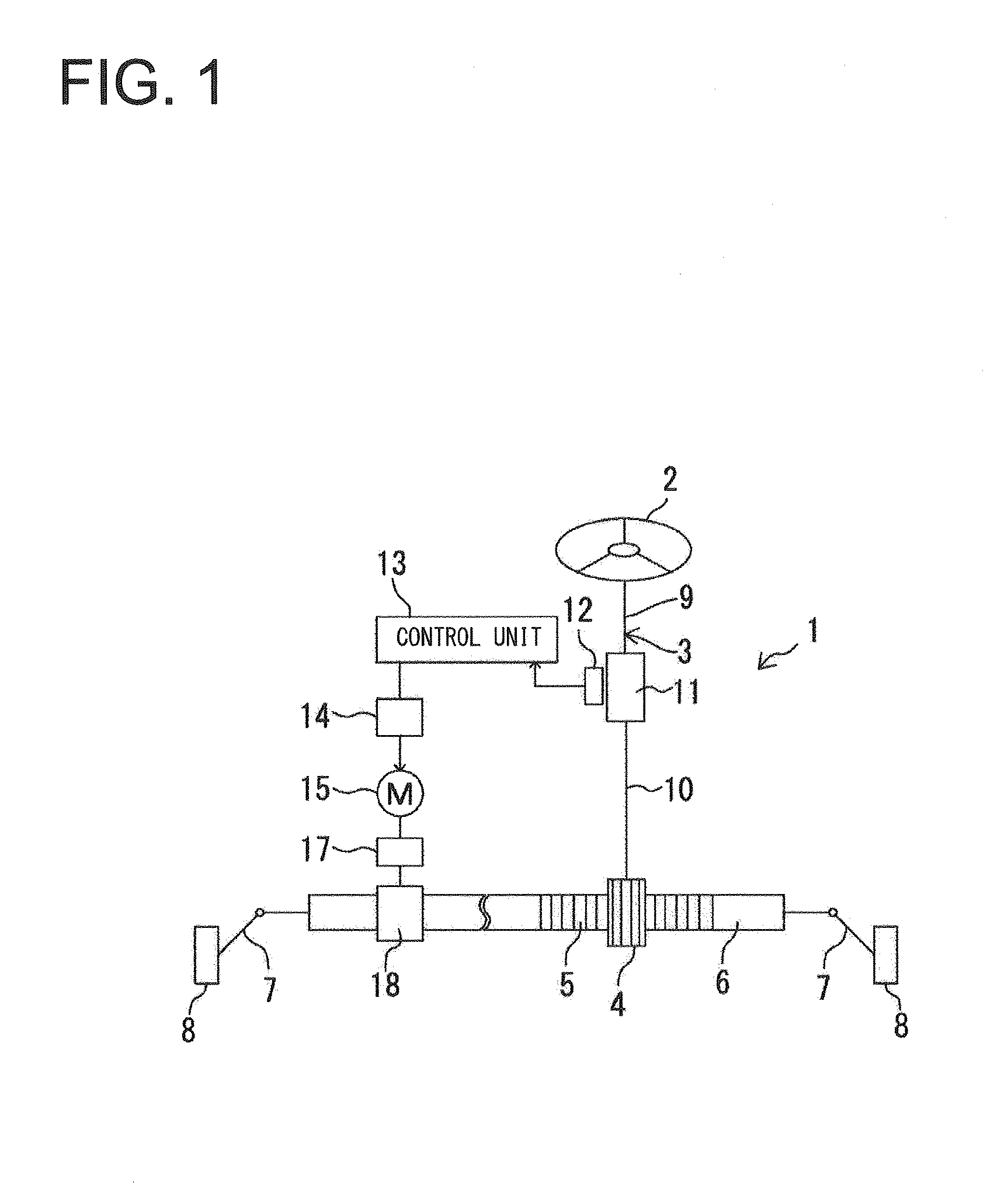
[0070]Explanations about the elements of an electric power steering device along with further explanations about the operation of such a device will be provided here. As shown in FIG. 1, the electric power steering device (EPS) (1) includes: a steering shaft (shaft) (3) connected to a steering wheel (2) as a steering component; and a rack shaft (6) having a pinion gear (4) disposed on an end of the steering shaft (3) and a rack gear (5) engaged with the pinion gear (4), where the rack shaft (6) can serve as a steering shaft extended in a lateral direction of the vehicle.

[0071]The rack shaft (6) has tie rods (7) connected to both ends thereof, respec...

second embodiment

[0110]Next, hereinafter, a shaft structure (spline) as well as a male component (male spline shaft) and a female component (female spline shaft), both components making up the shaft structure, in a second embodiment of the present invention will be described with reference to FIGS. 7-12. Note that detailed descriptions of the parts (101) to (115), (117), and (118) in the second embodiment will be omitted because they are the same as the above-described parts (1) to (15), (17), and (18) in the first embodiment, respectively.

[0111](Outlined Structure of Electric Power Steering Device)

[0112]As shown in FIG. 7, the electric power steering device (EPS) (101) includes: a steering shaft (shaft) (103) connected to a steering wheel (102) as a steering component; and a rack shaft (106) having a pinion gear (104) disposed on an end of the steering shaft (103) and a rack gear (105) engaged with the pinion gear (104), where the rack shaft (106) can serve as a steering shaft extended in a lateral...

third embodiment

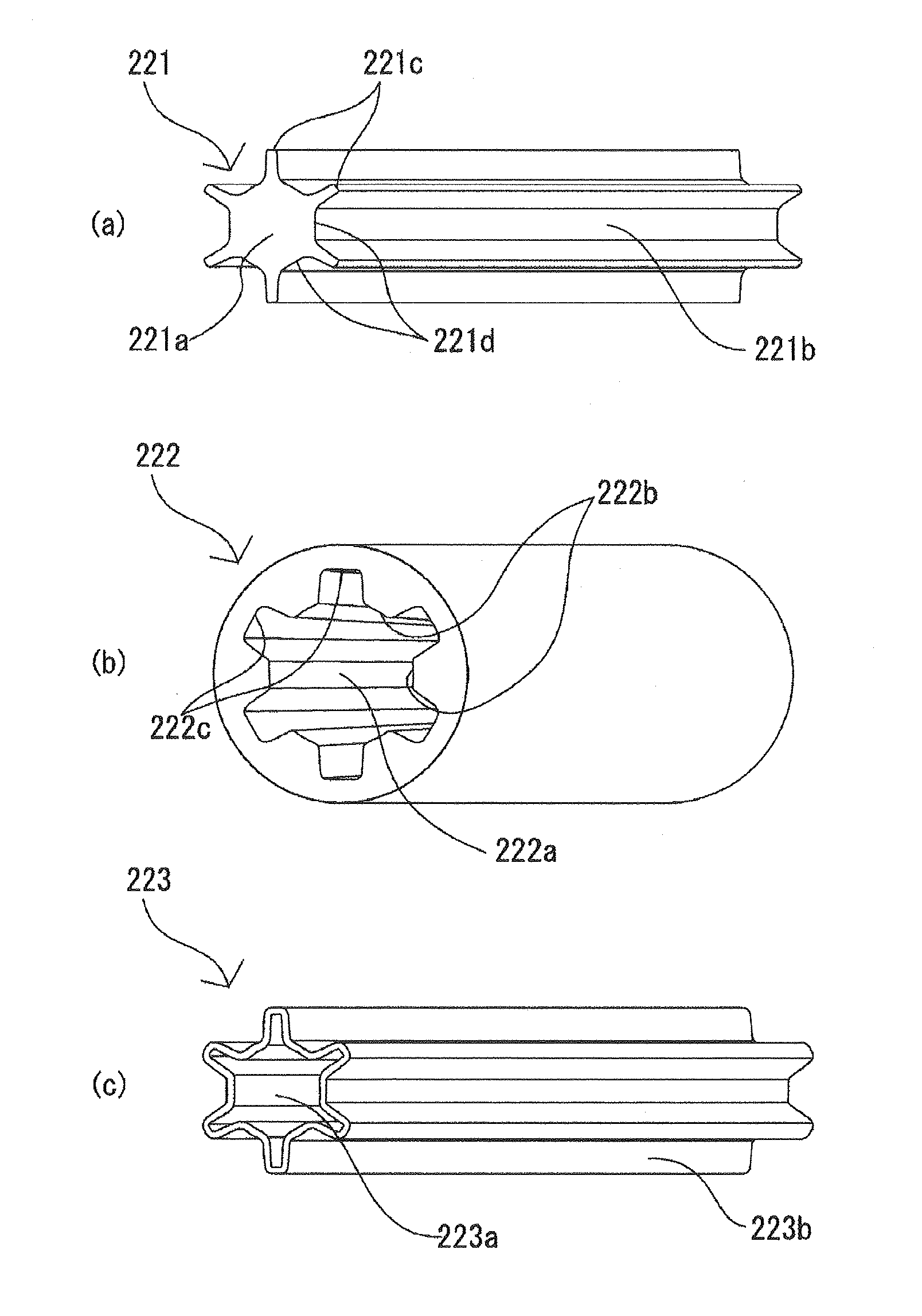
[0139]Next, hereinafter, a shaft structure (spline) as well as a male component (male spline shaft) and a female component (female spline shaft), both components making up the shaft structure, in a third embodiment of the present invention will be described with reference to FIGS. 13-18. Note that detailed descriptions of the parts (201) to (215), (217), and (218) in the second embodiment will be omitted because they are the same as the above-described parts (1) to (15), (17), and (18) in the first embodiment, respectively.

[0140](Outlined Structure of Electric Power Steering Device)

[0141]As shown in FIG. 13, the electric power steering device (EPS) (201) includes: a steering shaft (shaft) (202) connected to a steering wheel (203) as a steering component; and a rack shaft (206) having a pinion gear (204) disposed on an end of the steering shaft (203) and a rack gear (205) engaged with the pinion gear (204), where the rack shaft (206) can serve as a steering shaft extended in a latera...


PUM


Abstract

A shaft structure including: a male component having male spline parts and male spline bottom parts on an outer peripheral part; a female component having female spline parts and female spline bottom parts on an inner peripheral part configured to allow the male component to be slidably inserted in an axial direction; and an elastic member arranged on the male component covering a surface of the outer peripheral part of the male component, wherein, in an initial state where the male component is inserted into the female component, the female and male components have first gaps between: sides of the female spline parts; and sides-facing portions of the elastic member, and when the male component is rotated, a time from the initial state to a state where the sides of the female spline parts abut on the portions of the elastic member, has predetermined time differences along the axial direction.

Description

CROSS REFERENCE TO RELATED APPLICATIONS[0001]This is a continuation application of International Patent Application No. PCT / JP2013 / 083152 filed on Dec. 11, 2013 claiming priority upon Japanese Patent[0002]Application Nos. 2012-272886 and 2013-251755 filed on Dec. 13, 2012 and Dec. 5, 2013, respectively, of which full contents are incorporated herein by reference.BACKGROUND OF THE INVENTION[0003]1. Field of the Invention[0004]The present invention relates to a shaft structure to be installed in shafts used for various industrial machines, and a male component and a female component included in the shaft structure.[0005]2. Description of the Background Art[0006]Conventionally, there have been publicly well-known telescopic shafts each including male and female spline shafts to be incorporated into vehicle steering shafts (see FIG. 2 in Patent Document 1). Such a telescopic shaft has splines formed on an outer surface of the male spline shaft and an inner surface of the female spline s...

Claims


Application Information

Patent Timeline
Patent Type & Authority Applications(United States)
IPC IPC(8): F16B7/00
CPCF16B7/00B62D1/20F16D3/06F16D3/12B62D1/16F16D3/10F16D3/68F16D2001/103Y10T403/7026F16D1/06
Inventor ISHIZAKI, YOJIKIYOHARA, YOSHIHARUNAKAI, KATSUYUKIAOKI, KENICHIROAOKI, YASUHIRO
Owner NITTA CORP
Why Eureka
Try Eureka