Valve Stem and Valve Core Assembly and Valve Comprising the Assembly

Active Publication Date: 2015-10-01
EMERSON PROCESS MANAGEMENT REGULATOR TECH INC
View PDF10 Cites 13 Cited by
  • Summary
  • Abstract
  • Description
  • Claims
  • Application Information

AI Technical Summary

Benefits of technology

[0004]The present invention provides a valve stem and valve core assembly and a valve comprising the assemb

Problems solved by technology

Otherwise, situations of evaporation, emission, drip and leakage easily occur, the product quality is caused to be low, the energy consumption is increased, the equipment is corroded, the material consumption is increased, the environment is polluted and even accidents such as shutdown are caused.
At present, for most valves, in order to realize the closing function, a valve stem and a valve

Method used


Image

  • Valve Stem and Valve Core Assembly and Valve Comprising the Assembly
  • Valve Stem and Valve Core Assembly and Valve Comprising the Assembly
  • Valve Stem and Valve Core Assembly and Valve Comprising the Assembly

Examples


Example

Example 1

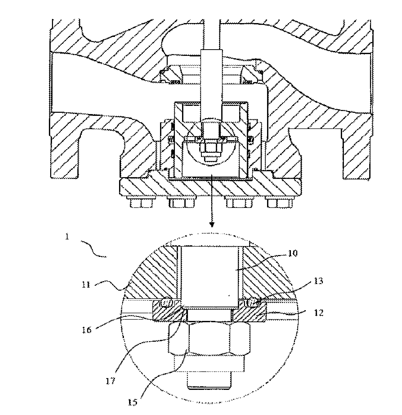
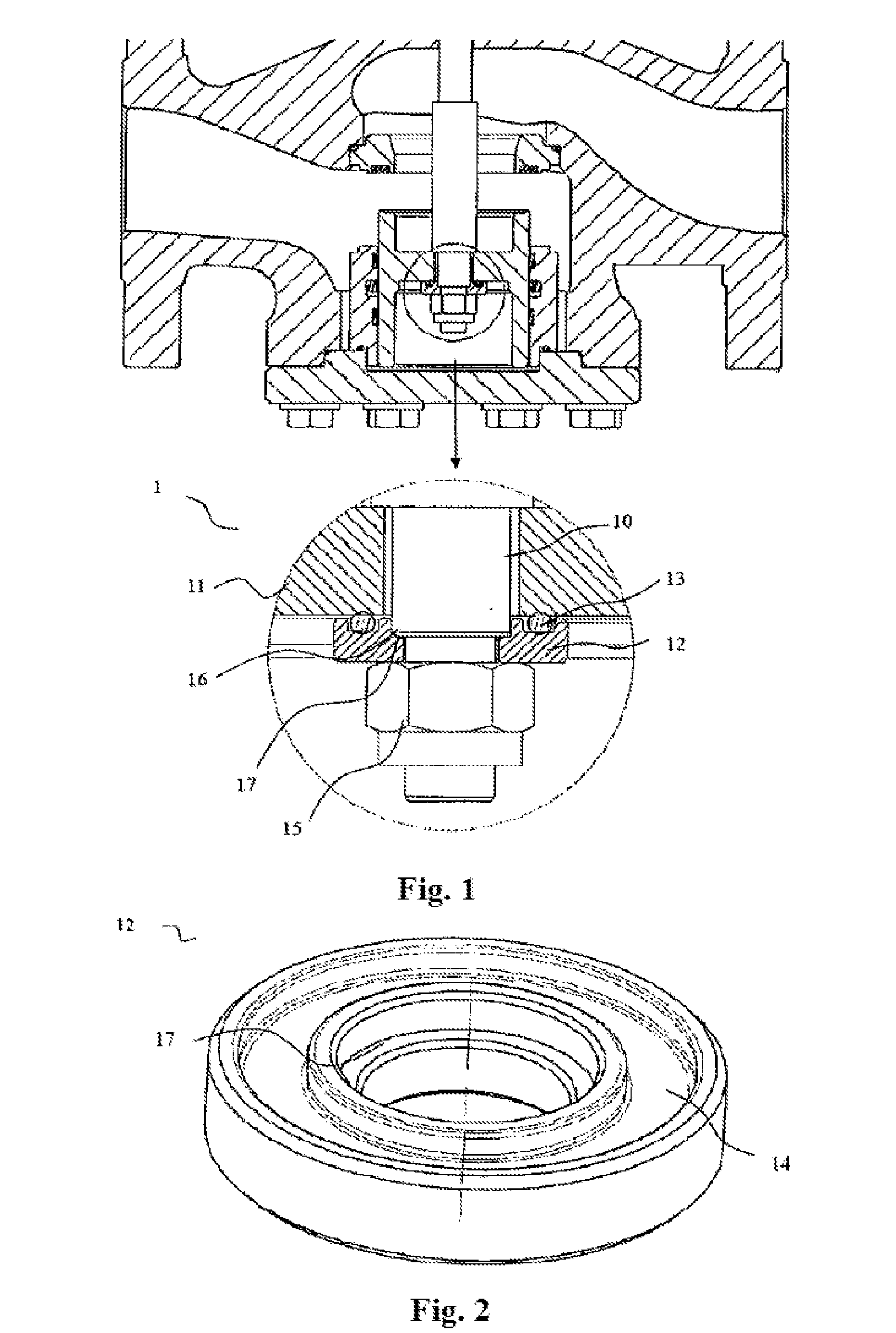
[0022]The example of the present invention provides a valve stem and valve core assembly. As shown in FIG. 1, the valve stem and valve core assembly 1 comprises a valve stem 10, a valve core 11 and an adjusting device 12, the valve core 11 and the adjusting device 12 sleeve the valve stem 10, the adjusting device 12 is located on the upper side or the lower side of the valve core 11, an elastic element 13 is arranged between the adjusting device 12 and the valve core 11, the adjusting device or the valve core is provided with a groove for containing the elastic element, and the elastic element 13 can be specifically made of rubber. Since the valve core 11 and the adjusting device 12 sleeve the valve stem 10, both the valve core 11 and the adjusting device 12 are provided with a center hole, wherein. the inner diameter of the contact part where the valve core is in contact with the valve stem is slightly larger than the outer diameter of the valve stem, so that the contact p...

Example

Example 2

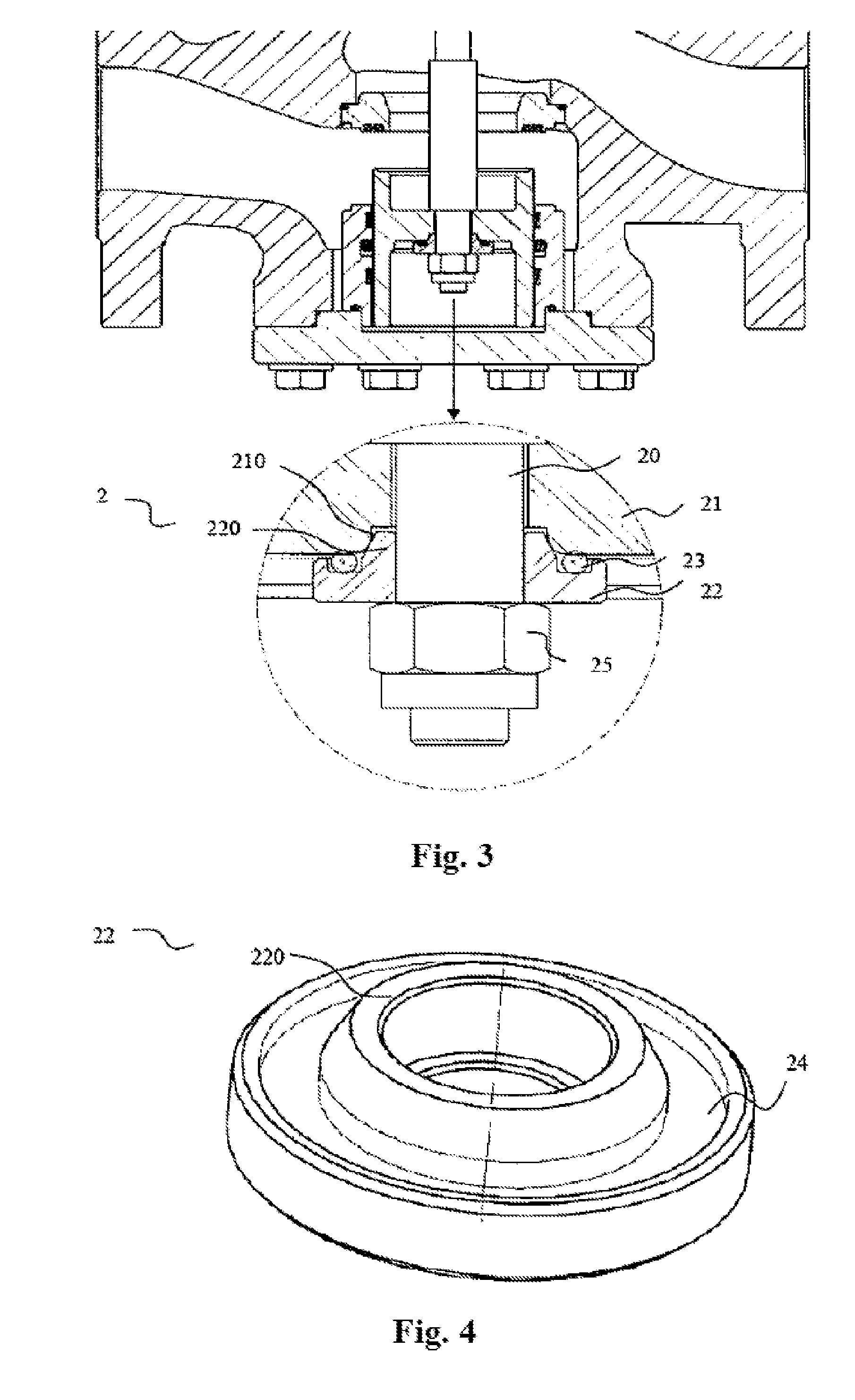
[0030]The example of the present invention provides a valve stem and valve core assembly. As shown in FIG. 3, the valve stem and valve core assembly 2 comprises a valve stem 20, a valve core 21 and an adjusting device 22, the valve core 21 and the adjusting device 22 sleeve the valve stem 20, the adjusting device 22 is located on the upper side or the lower side of the valve core 21, an elastic element 23 is arranged between the adjusting device 22 and the valve core 21, the adjusting device or the valve core is provided with a groove, the elastic element 23 is nested in the groove and the elastic element 23 can be specifically made of rubber. Since the valve core 21 and the adjusting device 22 sleeve the valve stem 20, both the valve core 21 and the adjusting device 22 are provided with a center hole. Wherein, the inner diameter of the contact part where the valve core is in contact with the valve stem is slightly larger than the outer diameter of the valve stem, so that t...

Example

Example 3

[0042]The example of the present invention provides a valve. The valve comprises the valve stem and valve core assembly of example 1 or example 2. The valve further comprises a valve port, one end of the valve stem and the valve core pass through the valve port, the valve core sleeves one end of the valve stem, the valve core moves under the drive of the valve stem, and when the valve core is in full contact with the valve port, a valve port closing state is formed.

[0043]The adjusting device of the valve sleeves the valve stem and is located on the upper side or the lower side of the valve core, an elastic element is arranged between the valve core and the adjusting device, and the elastic element is located in a groove in the valve core or the adjusting device.

[0044]According to the valve provided by the example of the present invention, due to the existence of the adjusting device and the elastic element, an axial clearance exists between the valve core and the adjusting ...


PUM


Abstract

The present invention relates to a valve stem and valve core assembly and a valve comprising the assembly. The valve core sleeves the valve stem, an adjusting device is arranged on the valve stem, an elastic element is arranged between the adjusting device and the valve core, and a clearance exists among the valve core, the valve stem and the adjusting device, so that the valve core can move relative to the valve stem and the valve can have a good closing performance.

Description

TECHNICAL FIELD[0001]The present invention relates to a valve stem and valve core assembly and a valve comprising the assembly.BACKGROUND ART[0002]A valve is a control device of a fluid pipeline. Its basic functions are to connect and cut off the circulation of medium in the pipeline, change the circulation of the medium, change the flowing direction of the medium and adjust the pressure or flow of the medium, so as to protect the normal operation of equipment on the pipeline. With the continuous development of modern industry, in view of the demands in aspects of petroleum, chemical industry, power stations, metallurgy, ships, nuclear energy and space navigation, higher requirements are put forward to valves and the demands are continuously increased. For one modern petrochemical plant, approximate ten thousand of various valves are needed. Since the use amount of valves is great and the valves are frequently opened and closed, the valves are required to have good closing performan...

Claims


Application Information

Patent Timeline
IPC IPC(8): F16K27/00
CPCF16K27/00F16K1/48F16K1/487F16K1/46F16K1/34
Inventor XIAO, XIAOHUO, PING
Owner EMERSON PROCESS MANAGEMENT REGULATOR TECH INC
Why Eureka
Try Eureka