Thermal storage control system and thermal storage body used in same

a control system and control system technology, applied in the direction of lighting and heating apparatus, heating types, domestic cooling apparatus, etc., can solve the problem of difficult heating of indoor spa

Inactive Publication Date: 2015-10-01
PANASONIC INTELLECTUAL PROPERTY MANAGEMENT CO LTD
View PDF29 Cites 19 Cited by
  • Summary
  • Abstract
  • Description
  • Claims
  • Application Information

AI Technical Summary

Benefits of technology

[0006]The present invention has been made in view of the above-described problem, and an object of the present invention is to provide a thermal storage control system and a thermal storage body used in the same which can control temperature efficiently using a plurality of thermal storage bodies.
[0018]As described above, in the present invention, as an effect of utilization of stored heat with selecting a pathway of the ventilation pathway including an efficient thermal storage body to control temperature of the indoor space based on a thermal condition of each of the plurality of thermal storage body, controlling the temperature of the indoor space efficiently using the plurality of thermal storage bodies is possible.

Problems solved by technology

However, it is difficult to heat the indoor space even if a stored heat of a low temperature thermal storage body is recovered because recoverable heat quantity is small.

Method used


Image

  • Thermal storage control system and thermal storage body used in same
  • Thermal storage control system and thermal storage body used in same
  • Thermal storage control system and thermal storage body used in same

Examples


first embodiment

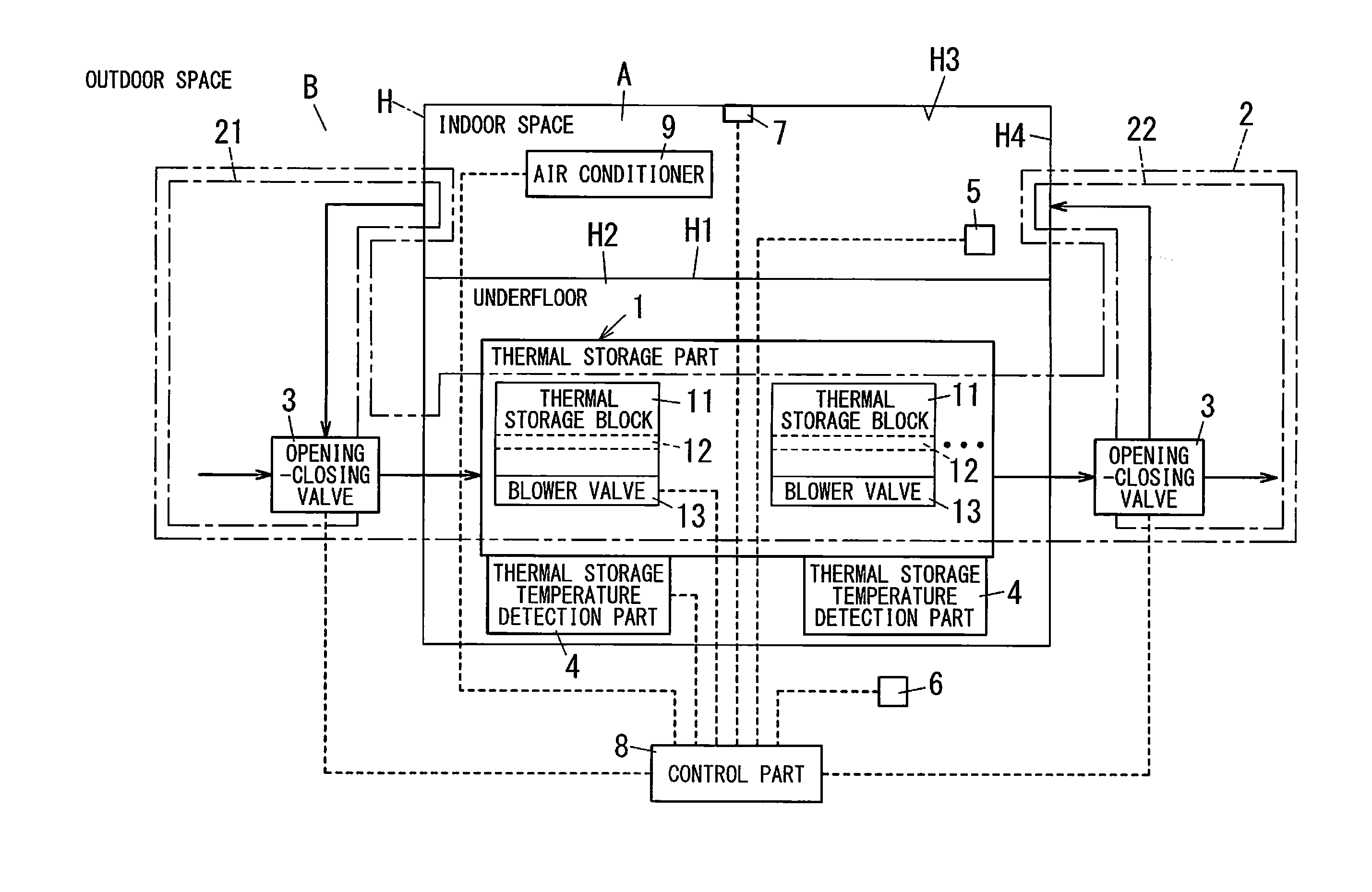
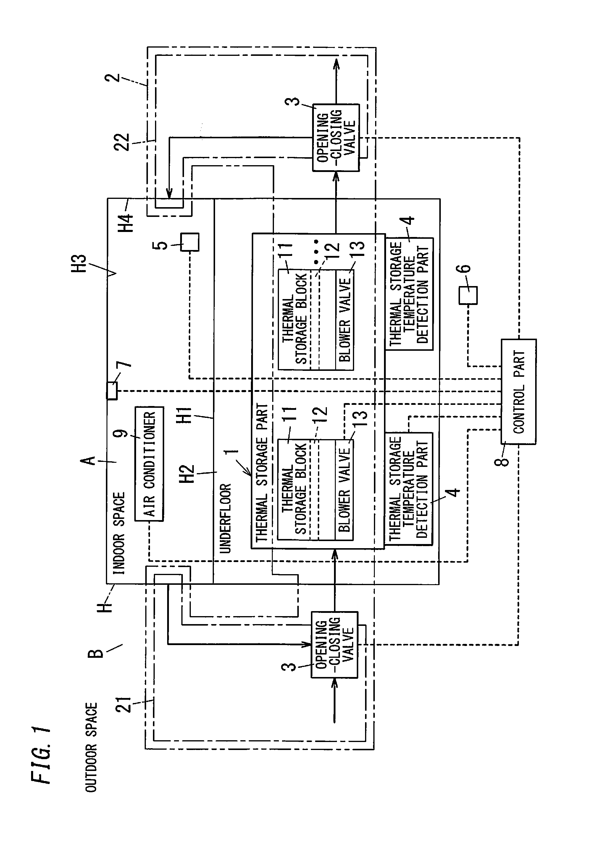
[0026]As shown in FIG. 1, a thermal storage control system of the present embodiment controls a thermal environment of an indoor space A in a building H, and includes a thermal storage part 1, a ventilation pathway 2, a plurality of opening-closing valves 3 (opening-closing members), a plurality of thermal storage body temperature detection parts 4, an indoor temperature detection part 5, an outdoor temperature detection part 6, a human detection part 7, and a control part 8.

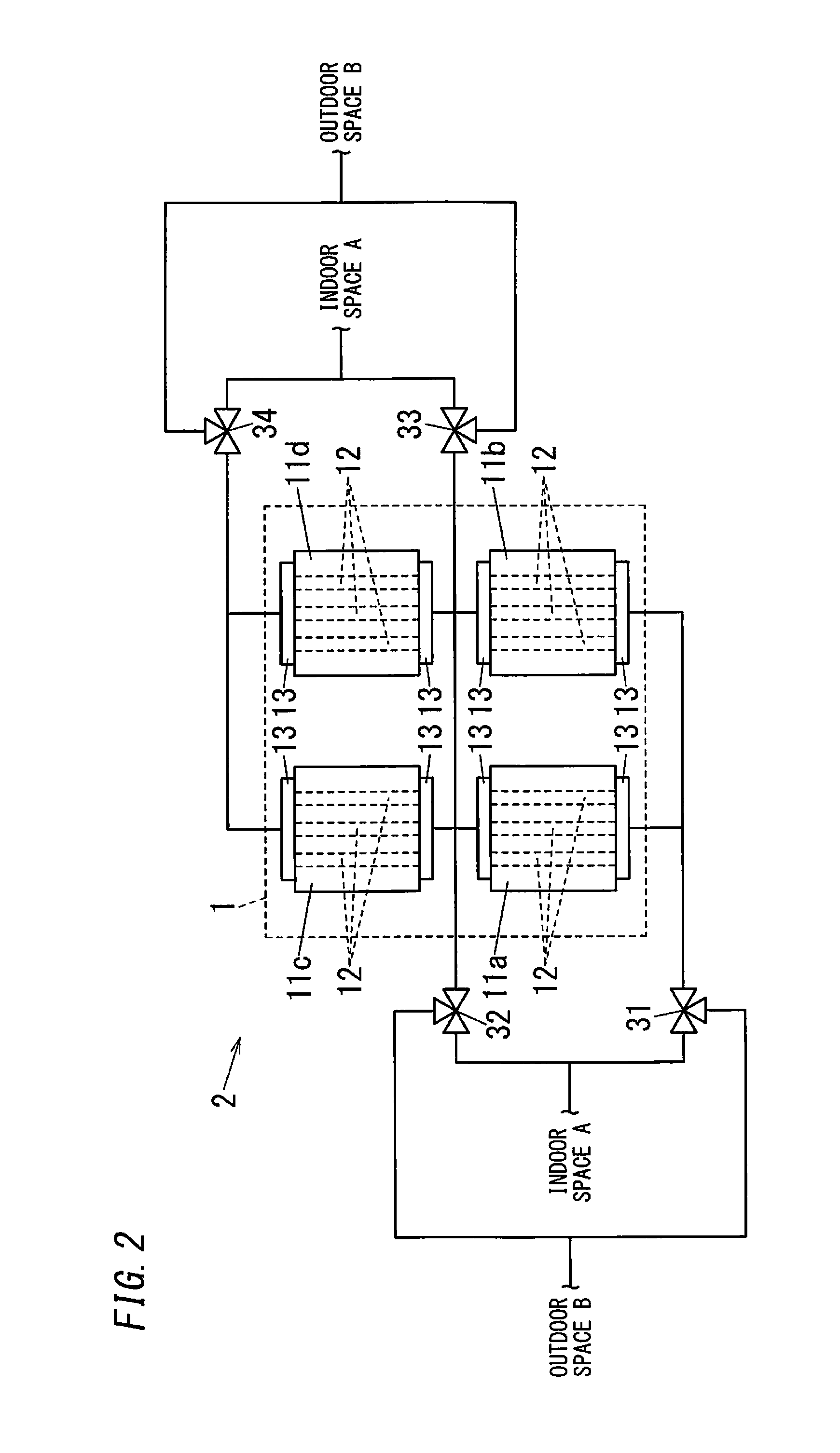
[0027]The thermal storage part 1 includes a plurality of thermal storage blocks 11 (thermal storage bodies), and the plurality of thermal storage blocks 11 are arranged along a flooring surface H1 (constituent face) in a space H2 under a floor in the building H. In the present embodiment, as shown in FIG. 2, four thermal storage blocks 11a to 11d as the plurality of thermal storage blocks 11 are arranged in two rows by two columns along the flooring surface H1. Note that, when the four thermal storage blocks 11 ...

second embodiment

[0098]A thermal storage control system of the present embodiment has a ventilation pathway 2 including a structure shown in FIG. 5. Constituent elements similar to first embodiment are assigned with same reference numerical, and descriptions thereof will be omitted.

[0099]A plurality of thermal storage blocks 110a to 110d constituting the ventilation pathway 2 of the present embodiment are the thermal storage blocks 11 without the blower valves 13. Also, in FIG. 5, six opening-closing valves 111 to 114, 121, and 122 are connected to the four thermal storage blocks 110a to 110d which are arranged in two rows by two columns. Note that, the opening-closing valves 111 to 114 are formed with two-way valve, and the opening-closing valves 121 and 122 are formed with a three-way valve.

[0100]An outlet of the opening-closing valve111 is connected to inflow openings of ventilation holes 12 of each of the thermal storage blocks 110a and 110b, and an outlet of the opening-closing valve 112 is con...


PUM


Abstract

The thermal storage control system includes a plurality of thermal storage, a ventilation pathway, a plurality of opening-closing members, and a control part. The plurality of thermal storage bodies are each provided with ventilation holes. The ventilation pathway is formed to include the ventilation holes and has a plurality of pathways from a first end to a second end so that air passes from the first end to the second end. The plurality of opening-closing members is configured to open or close the ventilation pathway. The control part is configured to individually switch control the plurality of opening-closing members. The control part is configured to switch a pathway through which an indoor air passes in the ventilation pathway by individually controlling opening and closing of the plurality of opening-closing members based on temperature of each thermal storage body and temperature of the indoor air.

Description

TECHNICAL FIELD[0001]The present invention relates to a thermal storage control system and a thermal storage body used in the same.BACKGROUND ART[0002]There is a system of reducing an air conditioning load by storing heat in a thermal storage body positioned inside of a building, and recovering the heat stored in the thermal storage body using an indoor air as a heating medium during a time the air conditioning load being used. For example, warm or cool air is sent to a thermal storage body in an underfloor of a building, heat is stored in the thermal storage body through a heat exchange, the heat stored in the thermal storage body is recovered using an indoor air as a heating medium, and then the air in the underfloor is returned to an indoor space through an opening-closing valve (damper) provided on the floor (for example, see JP 05-98718 A).[0003]Also, there are thermal storage bodies that are configured by arranging concrete blocks having ventilation holes (for example, see JP ...

Claims


Application Information

Patent Timeline
Patent Type & Authority Applications(United States)
IPC IPC(8): F24D11/00F28D20/00
CPCF28D20/00F24D11/006F28D20/0056F28D2020/0069F24F5/0017F24D5/02F24D19/1084F24D2220/006Y02E60/14
Inventor MURO, NAOKIYABUNOUCHI, NOBUAKITAKAHASHI, HAYATO
Owner PANASONIC INTELLECTUAL PROPERTY MANAGEMENT CO LTD
Why Eureka
Try Eureka