

Optical beam steering for tunable laser applications
a technology of optical beams and lasers, applied in the field of optical beam steering, can solve the problems of vibration, difficult coupling to a single optical fiber, and only obtaining efficient coupling for the dfb laser at the center of the array
- Summary
- Abstract
- Description
- Claims
- Application Information
AI Technical Summary
Benefits of technology
Problems solved by technology
Method used
Image

Examples
Embodiment Construction
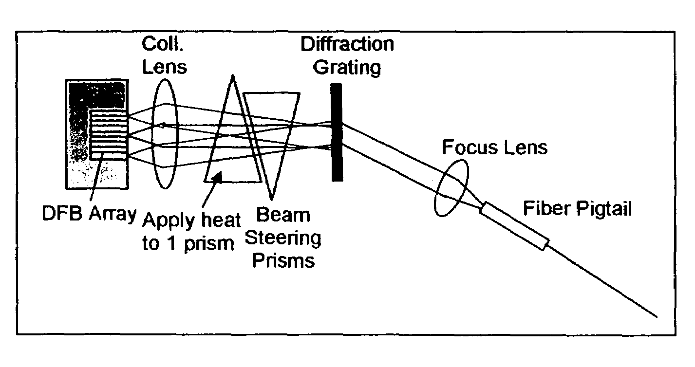
Beam Steering Using Thermo-optic Prism
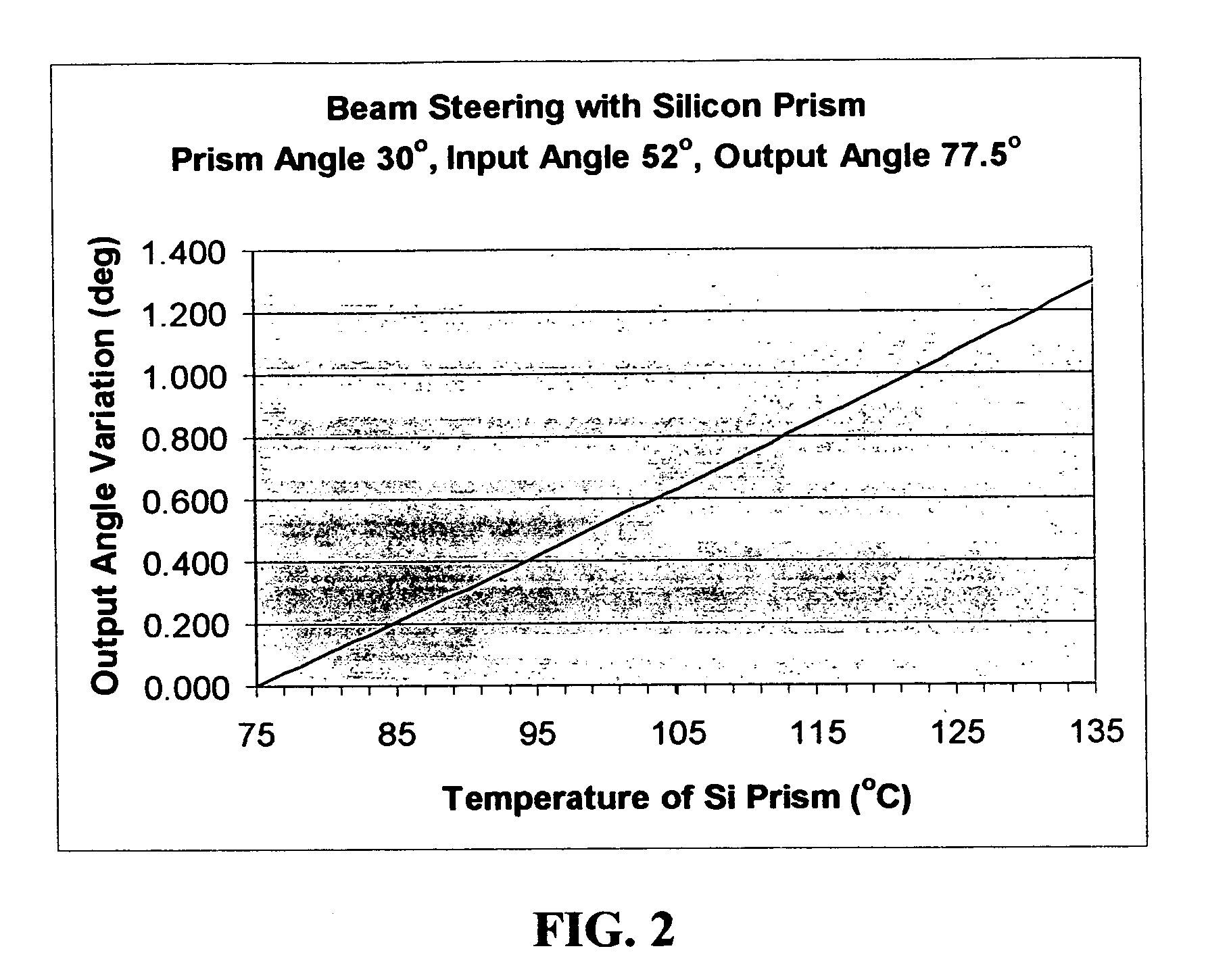
[0011]As described by the present invention, a thermally tuned beam steering element can be used in the optical path. A prism fabricated from a thermo-optic material can effectively act as an optical beam steering element by controlling the temperature. This beam steering element can be incorporated into various optical subassemblies to provide improved functionality e.g. wavelength tunable lasers.
[0012]This approach allows lower cost and simpler implementation while avoiding vibration-induced detrimental effects.
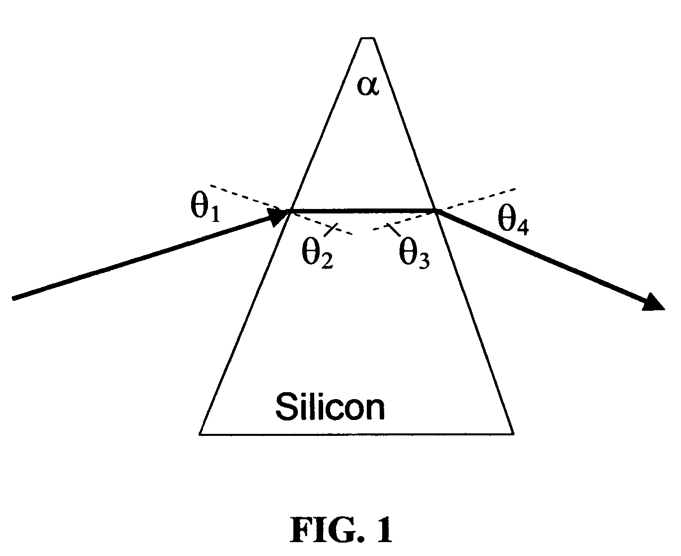
[0013]More particularly, by inserting a prism into the collimated beam path, it is possible to vary the angle of the beam by changing the refractive index of the prism material. Preferably, this can be done in an isotropic fashion by using a high dn / dT material such as a crystalline semiconductor such as Silicon, Gallium Arsenide or Indium Phosphide. Silicon is particularly convenient due to its ease of processing and low optical loss i...
PUM
| Property | Measurement | Unit |
|---|---|---|
| temperature | aaaaa | aaaaa |
| size | aaaaa | aaaaa |
| size | aaaaa | aaaaa |
Abstract
Description
Claims
Application Information