Expansion Valve

Inactive Publication Date: 2015-10-01
WENLING HENGFA AIRCONDITION COMPONENTS
View PDF7 Cites 12 Cited by
  • Summary
  • Abstract
  • Description
  • Claims
  • Application Information

AI Technical Summary

Benefits of technology

[0026]1. The structure is simple. The direction of the expansion valve can be controlled by controlling the pressure change of the cooling pipeline with a reversing valve.
[0027]2. The damping structure keeps the differences between the pressure of the inner cavity and the outlet and the inlet pressures balanced, and maintains the required pressure for refrigerant compressing and liquefying. Meanwhile, the valve cores keep static when the flow rate of the refrigerant is small, which reduces the frequent movements of the spring, and extends the service life of the components of the expansion valve.
[0028]3. The front damping chamber arising between the first valve core and the second valve core provides good cushion when the first valve core the second valve core contact each other, lightens the impacts and extends the service life of

Problems solved by technology

However, due to its higher cost, electronic expansion valve, sometimes, may be replaced by capillary tubes, and normal compressors by inverter compressors.
However, although this type of two-way expansion valve does entertain two-way flow, it is actually not meant for two-way flow.
When the flow is backwards, the refrigerant could

Method used


Image

  • Expansion Valve
  • Expansion Valve
  • Expansion Valve

Examples


first embodiment

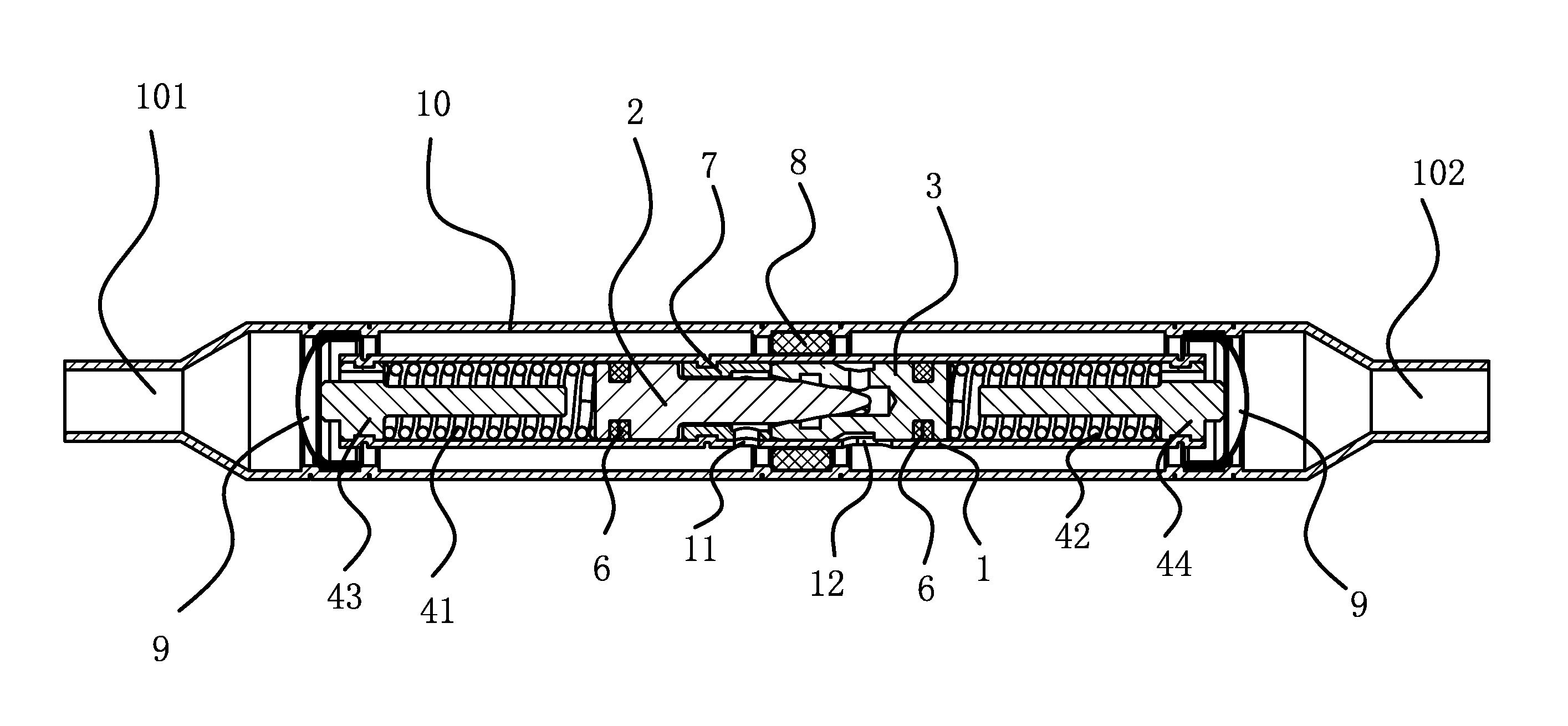
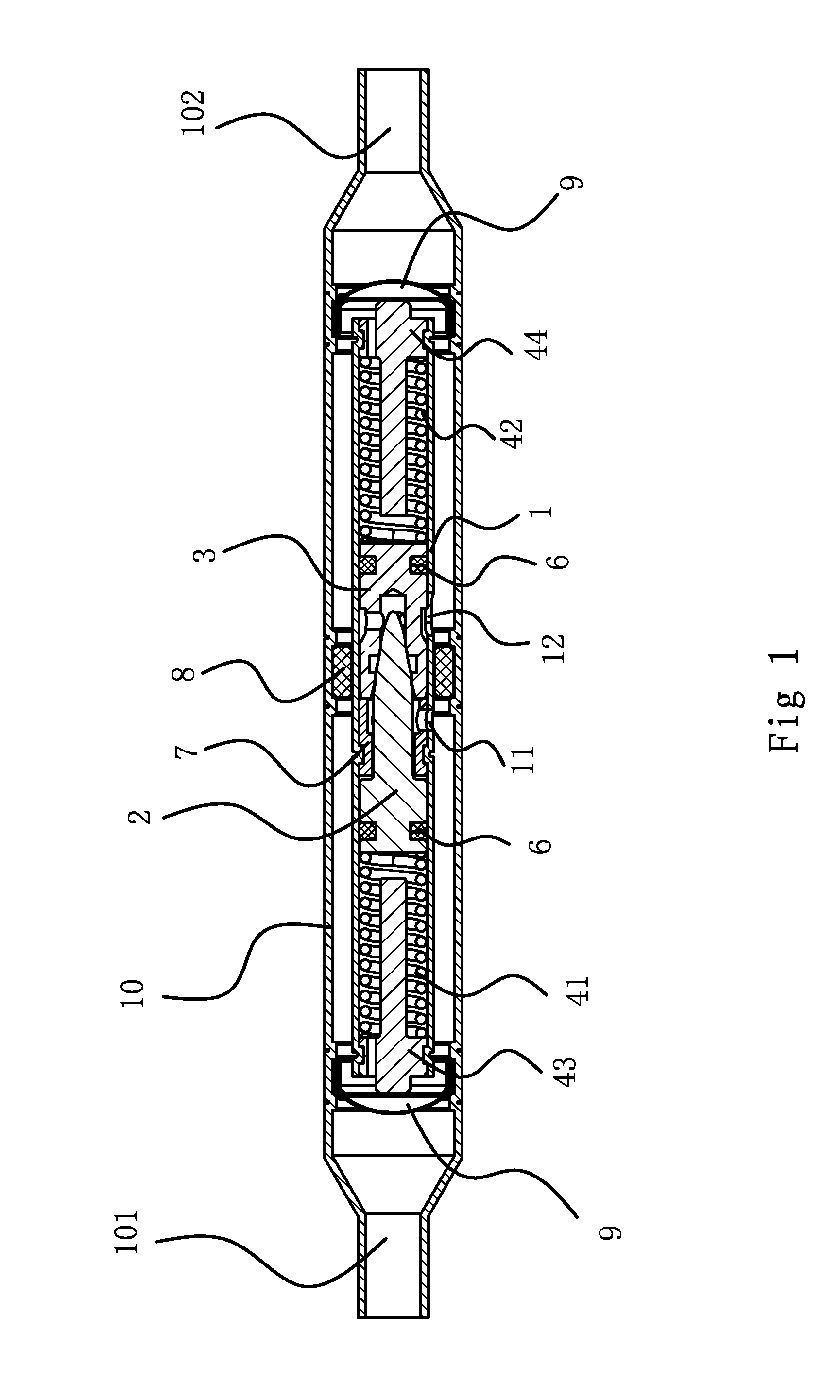
[0042]As shown in FIG. 1, An expansion valve comprises a housing (10) with an inlet end (101) and an outlet end (102), a cylindrical valve body (1) with an inner cavity fixed inside the housing (10), on the side of the valve body (1) wall there are an inlet (11) and an outlet (12) connecting the inner cavity and housing (10), and a spacer sleeve (8) between the housing (10) and valve body (1) that separates the inlet (11) and outlet (12). In the inner cavity, there is a matched set of the first valve core (2) and the second valve core (3) sliding along its inside. A retaining ring (7) is fixed to the mid-section of the inner cavity between the two valve cores. At both ends of the inner cavity there are spring assemblies pressing the first valve core (2) and the second valve core (3) towards the retaining ring (7). A damping structure is provided between the first valve core (2) and the second valve core (3).

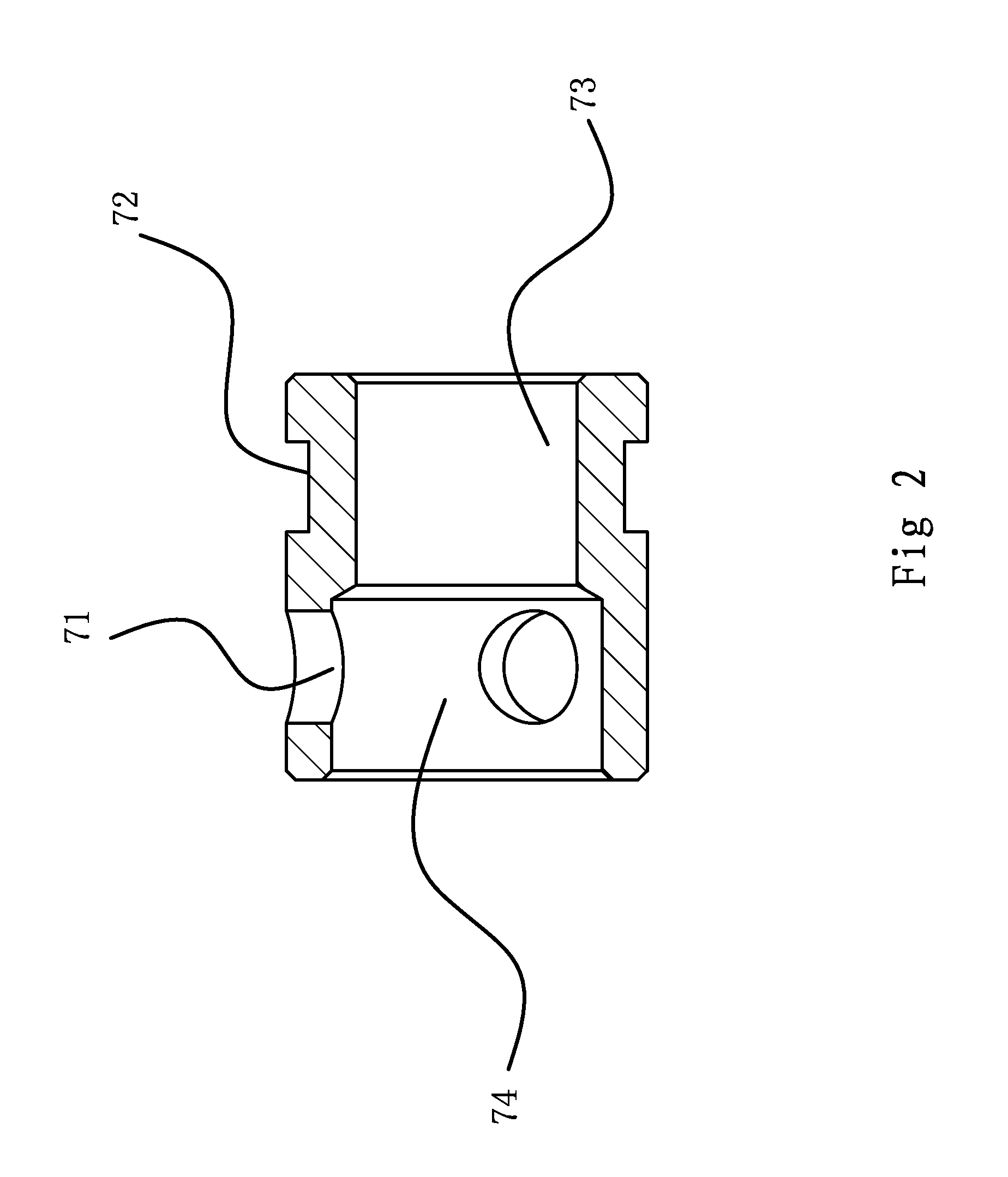
[0043]Specifically, as shown in FIGS. 1 through 5, the retaining ring (7) co...

second embodiment

[0053]The principle and structure of this embodiment are substantially similar to that of the first preferred embodiment. As shown in FIG. 6, the difference from the first preferred embodiment is that a flow path for small flow is added. Its structure comprises a vent (34) on the second valve core (3), connecting the outside of the valve body (1) and the relief groove (33). Capillary tubes are installed in the trough hole (34). The flow rate of the vent (34) can be changed by installing capillary tubes.

third embodiment

[0054]The principle and structure of this embodiment are substantially similar to that of the second preferred embodiment. As shown in FIG. 7, the difference from the second preferred embodiment is in the flow path for small flow. Its structure comprises a diversion slot (27) on the first valve core (2), connecting the relief groove (33) and the front cylinder bore (36).


PUM


Abstract

An expansion valve relating to the field of air conditioning technology. The present expansion valve comprises a housing, a cylindrical valve body with an inner cavity fixed inside the housing. In the inner cavity, there is a matched set of the first valve core and the second valve core sliding along it. A retaining ring is fixed in the inner cavity between the two valve cores. At both ends of the inner cavity there are spring assemblies driving the valve cores towards the retaining ring. A damping structure is also installed between the first valve core and the second valve core. In this manner, a cushioning effect is provided when the first valve core approaches the second valve core, which lightens the impacts to valve cores and thereby extend the service life of the expansion valve.

Description

BACKGROUND OF THE INVENTION[0001]1. Field of Invention[0002]The present invention relates generally to the field of air conditioning technology, and more particularly to a mechanical and automatic valve for use in inverter air conditioning and refrigeration.[0003]2. Related Art[0004]The expansion valve is an important component of refrigeration systems, generally installed between the condenser and the evaporator. It enables the gas evaporated by the evaporator passing through the compressor, being pressurized and liquefied into liquid refrigerant at high temperature and high pressure, passing through its throttle orifice and getting throttled into atomized liquid refrigerant at low temperature and low pressure, and, then, the refrigerant absorbs heat in the evaporator to realize a cooling effect. The expansion valve controls the flow rate according to changes in superheat at the end of the evaporator, so as to prevent under utilization of the evaporator surface due to over restrict...

Claims


Application Information

Patent Timeline
IPC IPC(8): F25B41/06
CPCF25B2341/063F25B41/062F25B2500/12F25B41/325F25B41/38F25B41/33
Inventor JIN, GENGRUAN, YIBING
Owner WENLING HENGFA AIRCONDITION COMPONENTS
Why Eureka
Try Eureka