Power conversion apparatus

a power conversion and power conversion technology, applied in the direction of electric variable regulation, process and machine control, instruments, etc., can solve the problems of enormous voltage spikes on less coupling coefficient of the transformer, and huge voltage spikes of the other components of the circuit, so as to achieve the effect of enhancing the performance of the power conversion apparatus, avoiding the reduction of ensuring the efficiency of the transformer

Inactive Publication Date: 2015-10-01
HEP TECH
View PDF16 Cites 7 Cited by
  • Summary
  • Abstract
  • Description
  • Claims
  • Application Information

AI Technical Summary

Benefits of technology

[0022]The power conversion apparatus according to the present invention has the following advantages:
[0023](1) In one embodiment of the present invention, the power conversion apparatus uses the leakage energy recycling circuit to receive and store the leakage energy, and then feedback which to the transformer, so the energy transmission range of the power conversion apparatus can extend to the whole plane; therefore, the performance of the power conversion apparatus can be effectively enhanced.
[0024](2) In one embodiment of the present invention, the power conversion apparatus uses the leakage energy recycling circuit to receive and store the leakage energy instead of a buffer circuit, so the efficiency of the transformer will be not reduced by the buffer circuit and the waste heat due to the buffer circuit will no longer be generated, too.
[0025](3) In one embodiment of the present invention, the power conversion apparatus can transmit energy via a plurality of primary windings, so the power conversion apparatus can exactly transmit energy to all loadings even if these loadings are stacked. Therefore, the performance of the power conversion apparatus can be significantly enhanced.
[0026](4) In one embodiment of the present invention, the design of the power conversion apparatus is favorable for modularization; thus, it is possible to achieve higher power transmission range by connecting multiple power conversion apparatuses rather than manufacturing a transformer with a large winding. In this way, the cost can be effectively reduced and the application can be more flexible, so the power conversion apparatus can have higher commercial value.

Problems solved by technology

With wider air gap between the primary winding and the secondary winding, the coupling coefficient of the transformer becomes lower, which generates more leakage energy.
Therefore, while a transformer works, the energy stored in the equivalent inductor of the primary winding is transferred to the secondary winding and the loading, but the energy stored in the leakage energy has no circuit path to go, which causes enormous voltage spikes on other components of the circuit.
But such buffer circuit may reduce the performance of the transformer.
However, for those power conversion apparatuses applied in wireless power transmission systems, the coupling coefficient would be greatly lowered with wider air gaps, and as a result, there would be much more leakage energy generated.
In such cases, the aforementioned design of buffer circuits would not only greatly reduce the performance of the transformer, but also generate great amount of waste heat due to absorbing and consuming the leakage energy.
The lifespans of the transformer itself and other components of the circuit tend to be shortened because of high temperature.
Moreover, due to the above reasons, the energy transmission range of the conventional power conversion apparatus is very small; therefore, the conventional power conversion apparatus can transmit power to the loading only when the loading is very close to the conventional power conversion apparatus rather than transmit power to the whole plane.
Thus, the conventional power conversion apparatus will not be able to transmit power to several loadings when these loadings are stacked.
Obviously, the performance of the conventional power conversion apparatus cannot be effectively improved and its application is also limited.
Therefore, it has become an important issue to provide a power conversion apparatus capable of solving the problems that the conventional power conversion apparatus has low efficiency, short lifespan, poor performance and limited application.

Method used


Image

  • Power conversion apparatus
  • Power conversion apparatus
  • Power conversion apparatus

Examples


first embodiment

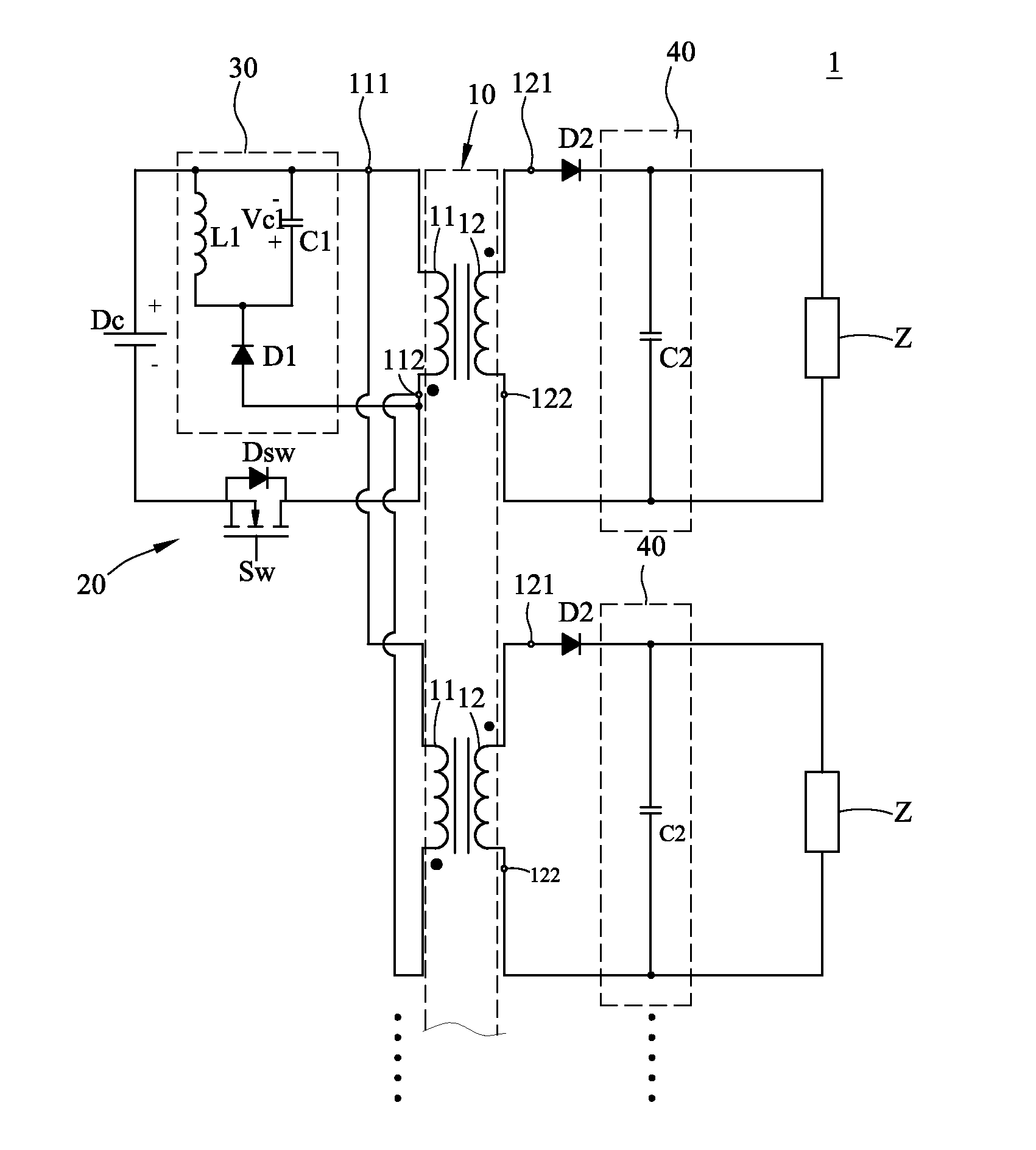
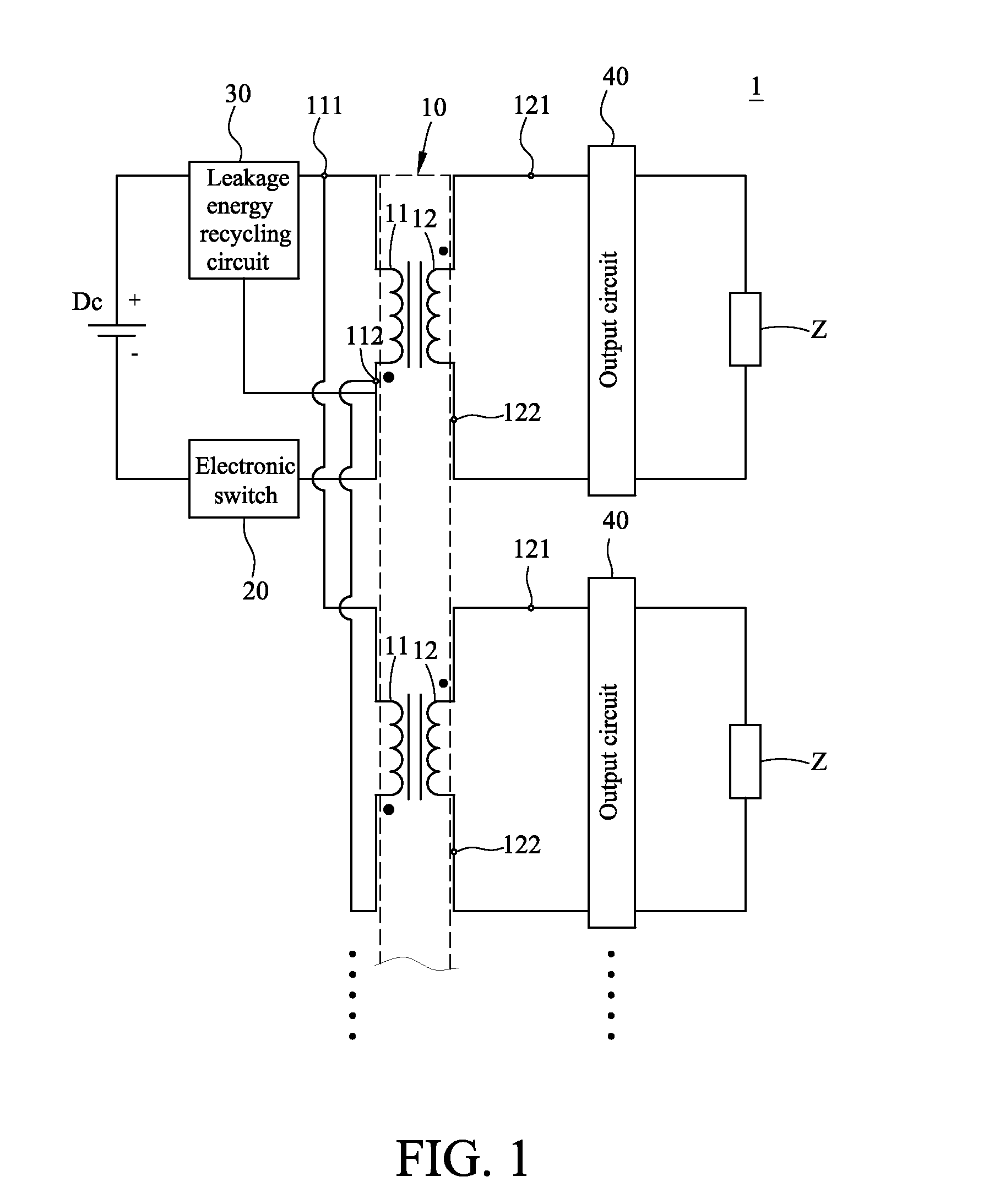
[0037]Please refer to FIG. 1, which is the schematic view of the power conversion apparatus in accordance with the present invention. As shown in FIG. 1, the power conversion apparatus 1 is able to convert power of a direct current (DC) power supply Dc, and provide the converted power to a plurality of loadings Z. The power conversion apparatus 1 may include a transformer 10, an electronic switch 20, a leakage energy recycling circuit 30, and a plurality of output circuits 40.

[0038]The transformer 10 may include a plurality of primary windings 11 and a plurality of secondary windings 12, wherein the primary windings 11 may receive the power of the DC power supply Dc, and the secondary windings 12 may output the converted power. These primary windings 11 may be connected to each other in parallel to increase the energy transmission range. One end of the electronic switch 20 may be electrically connected to the primary windings 11; the other end of the electronic switch 20 may be elec...

second embodiment

[0044]Please refer to FIG. 2 and FIG. 3; FIG. 3 is the second schematic view of the power conversion apparatus in accordance with the present invention. With the aforementioned design, while the power conversion apparatus 1 is in operation, the primary windings 11 of the transformer 10 can be seen as an equivalent primary inductor Lm and an equivalent leakage inductor Lk connected to each other in series.

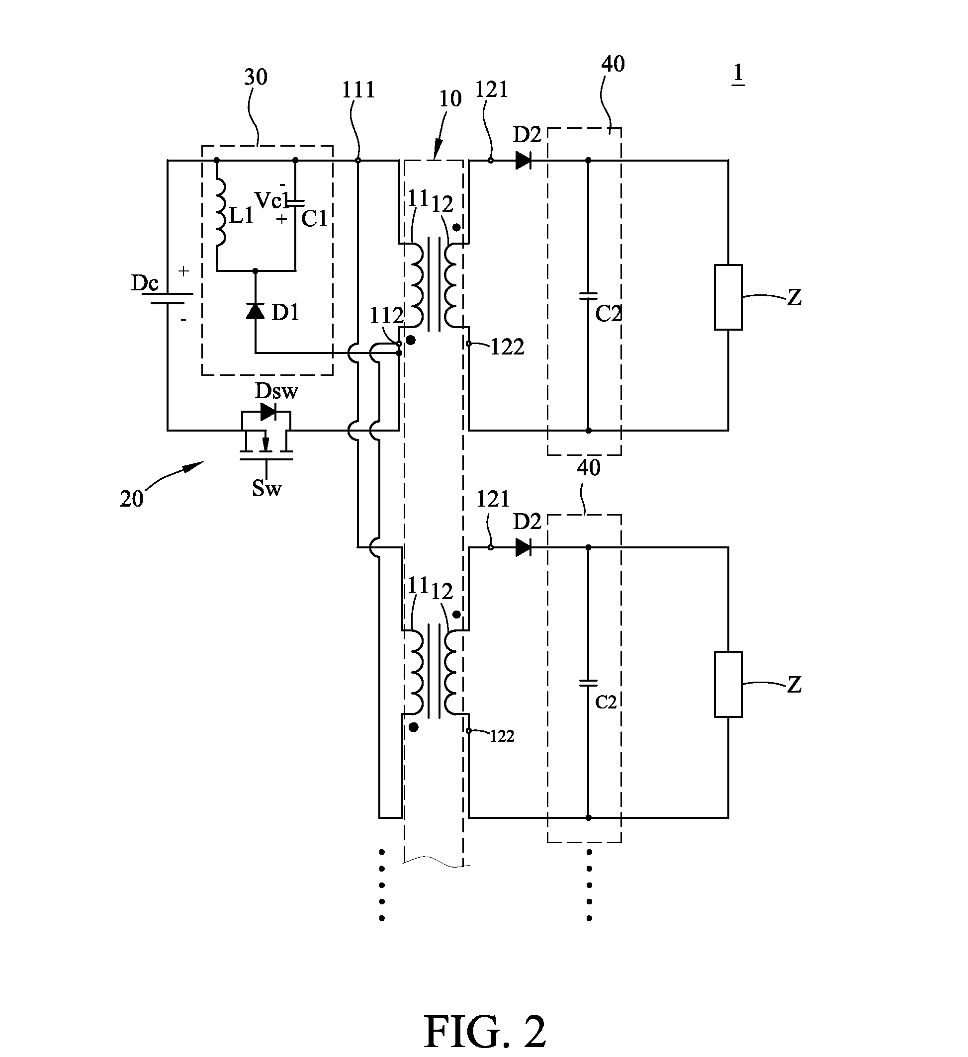
[0045]As shown in FIG. 3, when the electronic switch 20 allows the power of the DC power supply Dc to flow to the primary windings 11, the energy is stored in the equivalent primary inductor Lm and the equivalent leakage inductor Lk of the primary windings 11 through the electronic switch 20; at the same time, the second capacitor C2 may release energy to the corresponding loading Z. The first diode D1 may prevent the DC power supply Dc from directly charging the first capacitor C1 and the first inductor L1, and the second diode D2 may prevent the energy stored in the second capacit...

third embodiment

[0054]Please refer to FIG. 7, which is the schematic view of the power conversion apparatus in accordance with the present invention. FIG. 7 illustrates the usage situation of one embodiment of the power conversion apparatus according to the present invention. As shown in FIG. 7, the power conversion apparatus 1 can use a plurality of primary windings to transmit energy at the same time; accordingly, the power conversion apparatus can still effectively transmit energy to the loadings Z even if these loadings Z are stacked. Therefore, the above design can effectively improve the performance of the power conversion apparatus 1.


PUM


Abstract

A power conversion apparatus, which converts power of a DC power supply and provides it to a plurality of loadings, includes a transformer, an electronic switch, a leakage energy recycling circuit, and a plurality of output circuits. The transformer has a plurality of primary windings, which receives the power, and a plurality of secondary windings, which outputs the converted power. One end of the electronic switch is electrically connected to the primary windings; the other end thereof is electrically connected to the DC power supply. The leakage energy recycling circuit is electrically connected to the primary windings, and repeatedly and alternatively outputs the powers of positive and negative voltage. The circuit receives and stores leakage energy of the transformer, and feedbacks it to the transformer. The output circuits are electrically connected to the secondary windings to receive the converted power and to provide it to the loadings.

Description

CROSS-REFERENCE TO RELATED APPLICATION[0001]This application is a continuation-in-part application of U.S. application No. 14 / 324,722 filed on Jul. 7, 2014 and claiming priority from Taiwan patent application No. 103111703 filed on Mar. 28, 2014 and Taiwan patent application No. 104104123 filed on Feb. 6, 2015.BACKGROUND OF THE INVENTION[0002]1. Field of the Invention[0003]The present invention relates generally to power conversion, and more particularly to a power conversion apparatus capable of converting the power of a power supply to provide the converted power for a plurality of loadings.[0004]2. Description of the Related Art[0005]Typically, a conventional power conversion apparatus converts power with a transformer and other electronic components, and while the transformer works, it would generate corresponding magnetizing inductance and leakage energy, wherein leakage energy is a natural phenomenon which happens due to incomplete coupling of magnetic flux between the primary...

Claims


Application Information

Patent Timeline
Patent Type & Authority Applications(United States)
IPC IPC(8): H02M3/335
CPCH02M3/33507H02M3/33561Y02B70/10
Inventor CHEN, PO-YENPAN, CHING-TSAIHUNG, TA- SHENG
Owner HEP TECH
Why Eureka
Try Eureka