Image processing device, imaging device, image processing method and computer readable medium

a technology of image processing and imaging device, which is applied in the field of image processing device, imaging device, image processing method, and computer readable medium, can solve the problem that contrast cannot be displayed at a resolution greater, and achieve the effect of high precision movement of the focusing lens

Active Publication Date: 2015-10-01
FUJIFILM CORP
View PDF5 Cites 13 Cited by
  • Summary
  • Abstract
  • Description
  • Claims
  • Application Information

AI Technical Summary

Benefits of technology

[0026]The present invention is able to obtain the advantageous effect of enabling high precision movement of the focusing lens to the in-focus position to be performed quickly.

Problems solved by technology

However, in digital cameras with the reflex mirror omitted that have become prevalent in recent years, since there is no reflex mirror, there is no method to check the subject-image while displaying the phase difference, and contrast detection methods have had to be relied on.
However, in such cases, contrast cannot be displayed at a resolution greater than that of a display device, such as a Liquid Crystal Display (LCD), requiring adoption of methods such as enlarging a portion for display.

Method used


Image

  • Image processing device, imaging device, image processing method and computer readable medium
  • Image processing device, imaging device, image processing method and computer readable medium
  • Image processing device, imaging device, image processing method and computer readable medium

Examples


first exemplary embodiment

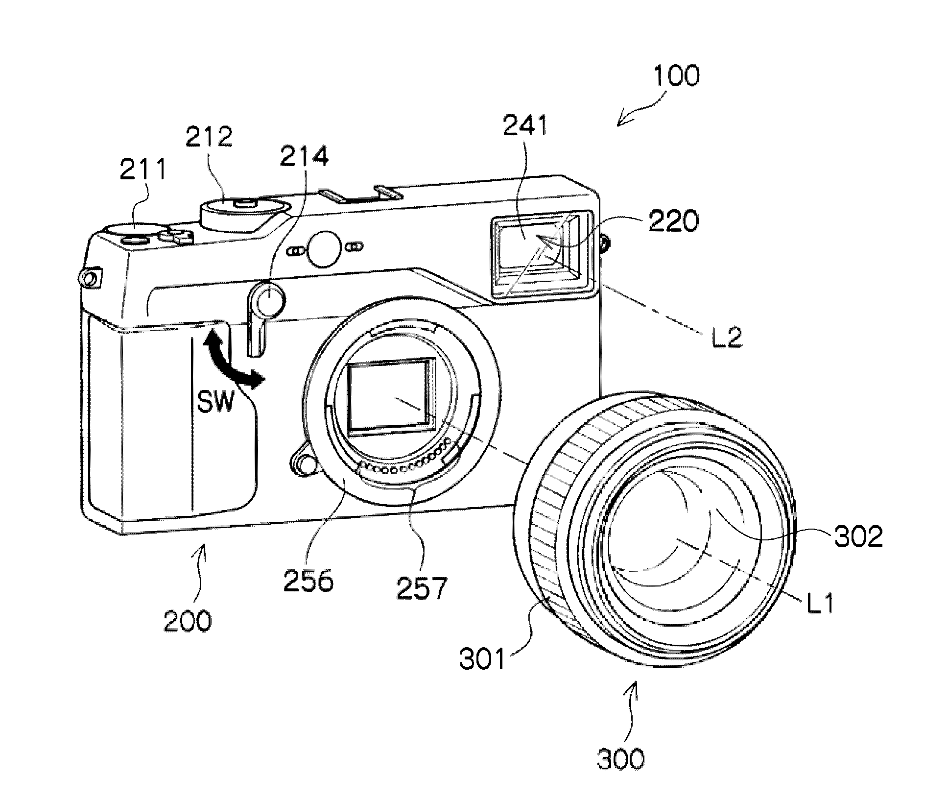
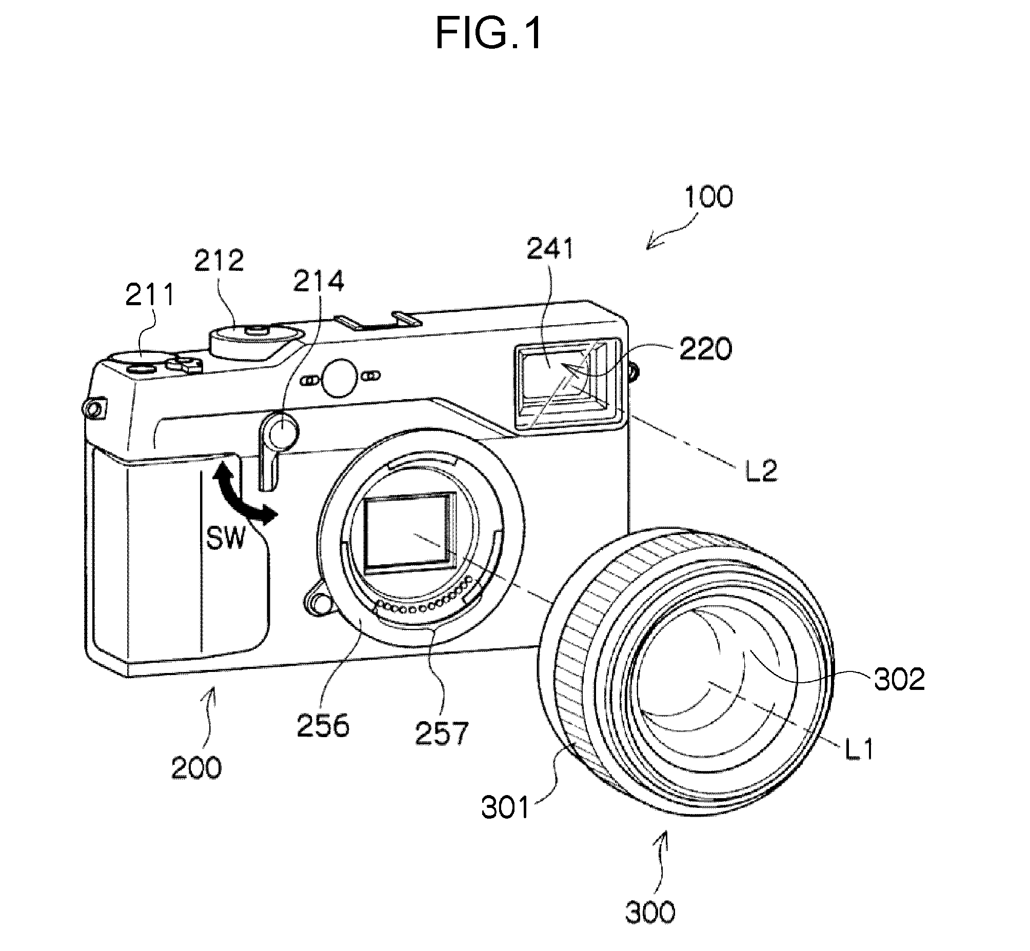
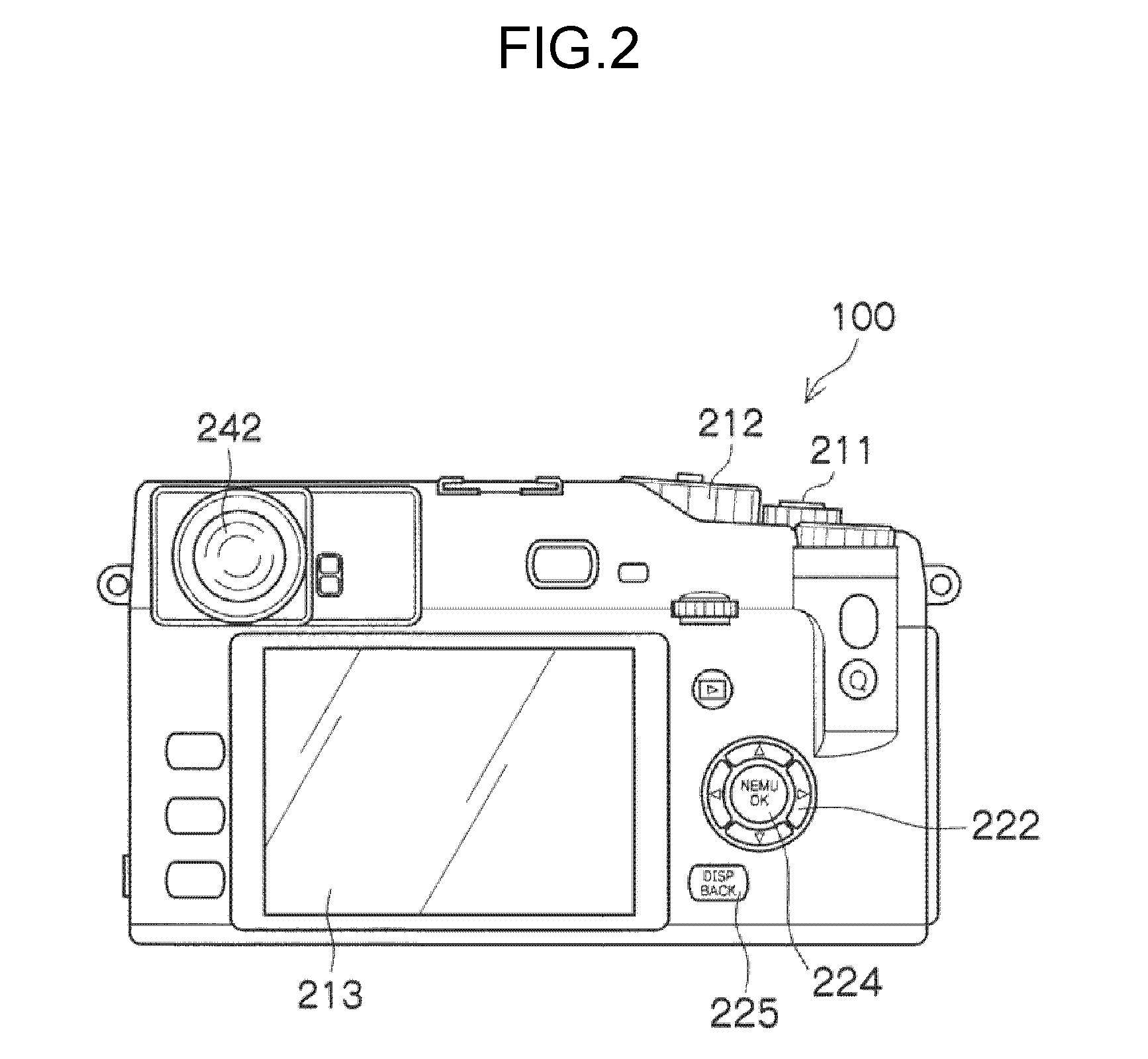
[0061]FIG. 1 is a perspective view illustrating an example of an external appearance of an imaging device 100 according to a first exemplary embodiment. FIG. 2 is a back view of the imaging device 100 illustrated in FIG. 1.

[0062]The imaging device 100 is an interchangeable lens camera. The imaging device 100 is a digital camera including a camera body 200 and an interchangeable lens 300 that is interchangeably mounted to the camera body 200, and without a reflex mirror. The interchangeable lens 300 includes imaging lenses 16 that include a focusing lens 302 capable of being moved along the optical axis direction by manual operation (see FIG. 3). A HYBRID FINDER (registered trademark) 220 is also provided to the camera body 200. The HYBRID FINDER 220 indicates, for example, a finder selectively employed as an optical viewfinder (referred to as “OVF” below), or as an electronic viewfinder (referred to as “EVF” below)

[0063]The interchangeable lens 300 is interchangeably mounted to the ...

second exemplary embodiment

[0186]Explanation has been given of an example of an embodiment in which movement of the focusing lens 302 is controlled using the operation movement ratio V. In the second exemplary embodiment, explanation follows regarding a case in which force to prevent rotation of the focus ring 301 (referred to below as resistance force) is employed in place of the operation movement ratio V. The same reference numerals are allocated to configuration members explained in the first exemplary embodiment, and further explanation is omitted thereof.

[0187]FIG. 24 illustrates an example of a configuration of an imaging device 100A according to the second exemplary embodiment. The imaging device 100A illustrated in FIG. 24 differs from the imaging device 100 explained in the first exemplary embodiment in the point that an interchangeable lens 300A is included instead of the interchangeable lens 300, and in the point that a camera body 200A is included instead of the camera body 200.

[0188]The intercha...

third exemplary embodiment

[0200]In each of the above exemplary embodiments, an example is given of the imaging device 100 (100A), however mobile terminal devices that are modified examples of the imaging device 100 include mobile phones and smartphones including a camera function, personal digital assistants (PDAs) and mobile gaming machines. Detailed explanation follows in the third exemplary embodiment regarding an example of a smartphone, with reference to the drawings.

[0201]FIG. 27 is a perspective view illustrating an example of the external appearance of a smartphone 500. The smartphone 500 illustrated in FIG. 27 includes a flat plate shaped casing 502, and a display and input section 520 provided on one face of the casing 502 and integrating together a display panel 521 serving as a display section and an operation panel 522 serving as an input section. The casing 502 includes a speaker 531, a microphone 532, an operation section 540, and a camera section 541. Note that the configuration of the casing...


PUM


Abstract

An image processing device comprising: a determination section that, based on a factor defining a depth representing a permissible range for acceptable state of focus and on parallax computed by a parallax computation section, determines an operation movement ratio for converting an operation amount, that instructs movement of a focusing lens, into a movement amount of the focusing lens by using a function including the operation movement ratio as a dependent variable and an independent variable determined according to the factor and the parallax; and a control section that controls a movement section to move the focusing lens by an amount equivalent to a movement amount determined based on an operation movement ratio determined by the determination section and the operation amount.

Description

CROSS-REFERENCE TO RELATED APPLICATIONS[0001]This application is a continuation application of International Application No. PCT / JP2013 / 078728, filed Oct. 23, 2013, the disclosure of which is incorporated herein by reference in its entirety. Further, this application claims priority from Japanese Patent Application No. 2012-277007, filed Dec. 19, 2012, the disclosure of which is incorporated herein by reference in its entirety.BACKGROUND[0002]1. Technical Field[0003]The present invention relates to an image processing device, an imaging device, an image processing method, and a computer readable medium.[0004]2. Background Art[0005]Digital cameras are widely known that are provided with autofocus, in which phase difference detection methods and contrast detection methods are employed, and also what is referred to as a manual focus mode, in which a user can manually perform focus adjustment.[0006]Digital cameras including a manual focus mode are known in which a reflex mirror is provi...

Claims


Application Information

Patent Timeline
Patent Type & Authority Applications(United States)
IPC IPC(8): H04N5/232
CPCH04N5/23212H04N5/23293H04N5/23222G02B7/34G03B13/36G03B17/18H04N23/672H04N23/633H04N25/704H04N23/843H04N25/134H04N23/64
Inventor INOUE, KAZUKI
Owner FUJIFILM CORP
Why Eureka
Try Eureka