
Row unit with integrated pressure source

a pressure source and unit technology, applied in the field of seed metering and unit containing the seed meter, can solve the problems of duplicate dispense, failure to dispense at all, and inability to achieve the effect of dispense,

Active Publication Date: 2015-10-08
KINZE MFG INC
View PDF1 Cites 33 Cited by
  • Summary
  • Abstract
  • Description
  • Claims
  • Application Information

AI Technical Summary

Benefits of technology

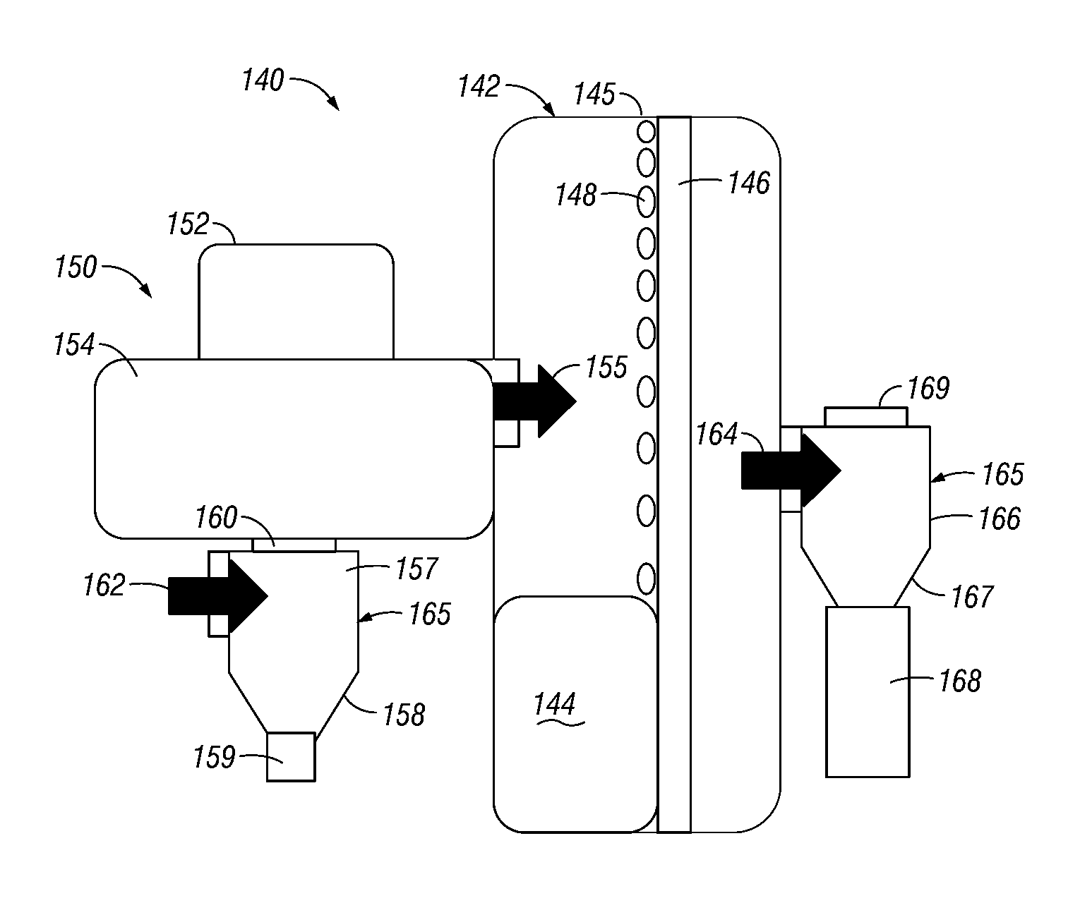
The invention provides an agricultural implement with a row unit that has an integrated pressure source for creating a pressure difference for the seed discs. This allows for better control and accuracy in cultivating seeds. Additionally, each seed disc has its own dedicated electric pressure source, ensuring consistent and efficient operation. The pressure source is powered by an electric motor and air source, and includes an air cleaning apparatus to ensure clean air is used. Overall, the invention improves the efficiency and effectiveness of agricultural cultivation.

Problems solved by technology

Although these mechanical seed meters are effective, they are limited in their ability to assure singulation of seeds and are prone to dispensing duplicates (i.e., multiple seeds) and / or failing to dispense at all (i.e., skips or misses).
A problem that exists with an air seed meter is that it can be difficult for the suction (negative) force or positive air force of the seed cell to draw or push seeds from a stagnant seed pool.
Another problem with air seed meters, and specifically the seed disc, is that seeds not released at or near the edge of the seed disc are susceptible to increased ricochet or bounce, thereby negatively impacting seed spacing.
This creates clutter on the planter, which increases with the number of row units and / or seed meters on a planter.
In addition, due to the sometimes long distances between the pressure source and the row unit, as well as the current state of and inefficiency of fans and vacuum distribution on planters, there may be a pressure drop, which can affect the efficiency of the fluid pressure at the row unit.

Method used


Image

  • Row unit with integrated pressure source
  • Row unit with integrated pressure source
  • Row unit with integrated pressure source

Examples


Embodiment Construction

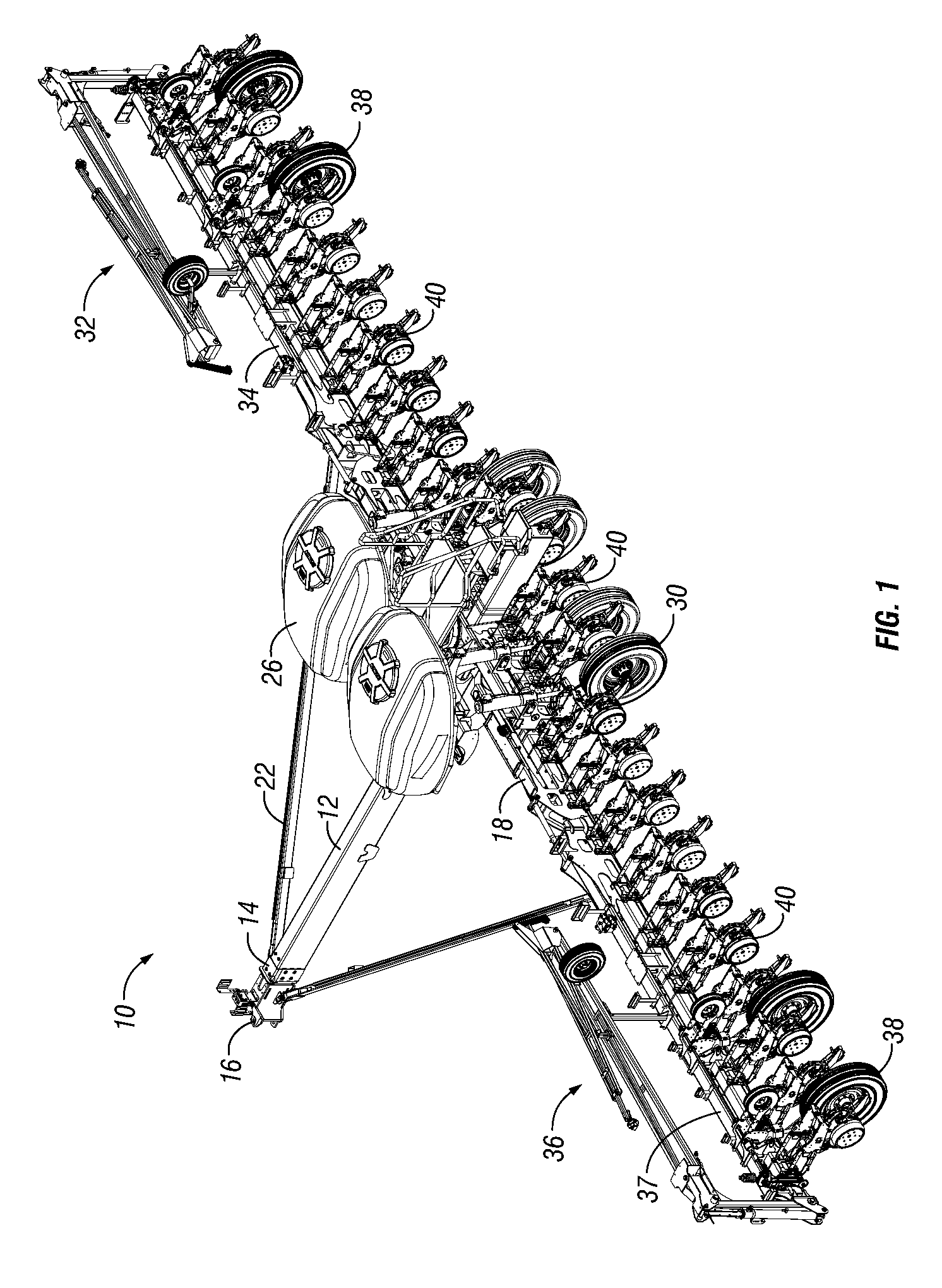
[0040]FIG. 1 is a perspective view of an exemplary embodiment of an agricultural implement 10, which is shown as a planting implement. Such a planter 10 is further shown and described in U.S. patent application Ser. No. 13 / 927,177, which is hereby incorporated in its entirety. FIG. 1 shows the planter 10 with a tongue 12, which may be a telescoping tongue when the planter 10 is a forward folding planter. A hitch 16 is positioned at the first end 14 of the tongue 12, and is used to attach the planting implement 10 to a tractor (not shown) or other vehicle for pulling the planting implement 10. When the tongue 12 is a telescoping tongue, it may be aided by the addition of draft links 22 on opposite sides of the tongue 12. The draft links 22 connect the tongue 12 to first and second wings 32, 36, such that when the wings fold by operation of cylinders, the draft links 22 will extend or retract sections of the telescoping tongue 12 to lengthen or shorten the tongue 12 so that the wings ...


PUM


Abstract

An agricultural planter includes a plurality of row units attached to a toolbar. The row units include seed meters in seed meter housings for receiving, singulating, and dispensing seed or other particulate. The seed meters include a circular seed disc with a seed path for receiving the seed in the seed meter housing. Integrated with the seed meter, such as at the housing, is an electric pressure source dedicated for providing a pressure differential for the seed meter or meters at a particular location on the planter. The pressure source can be positive or negative to temporarily adhere seed to the seed disc of the meter. A single pressure source can provide the pressure differential to a single meter or to multiple meters or discs at a row unit.

Description

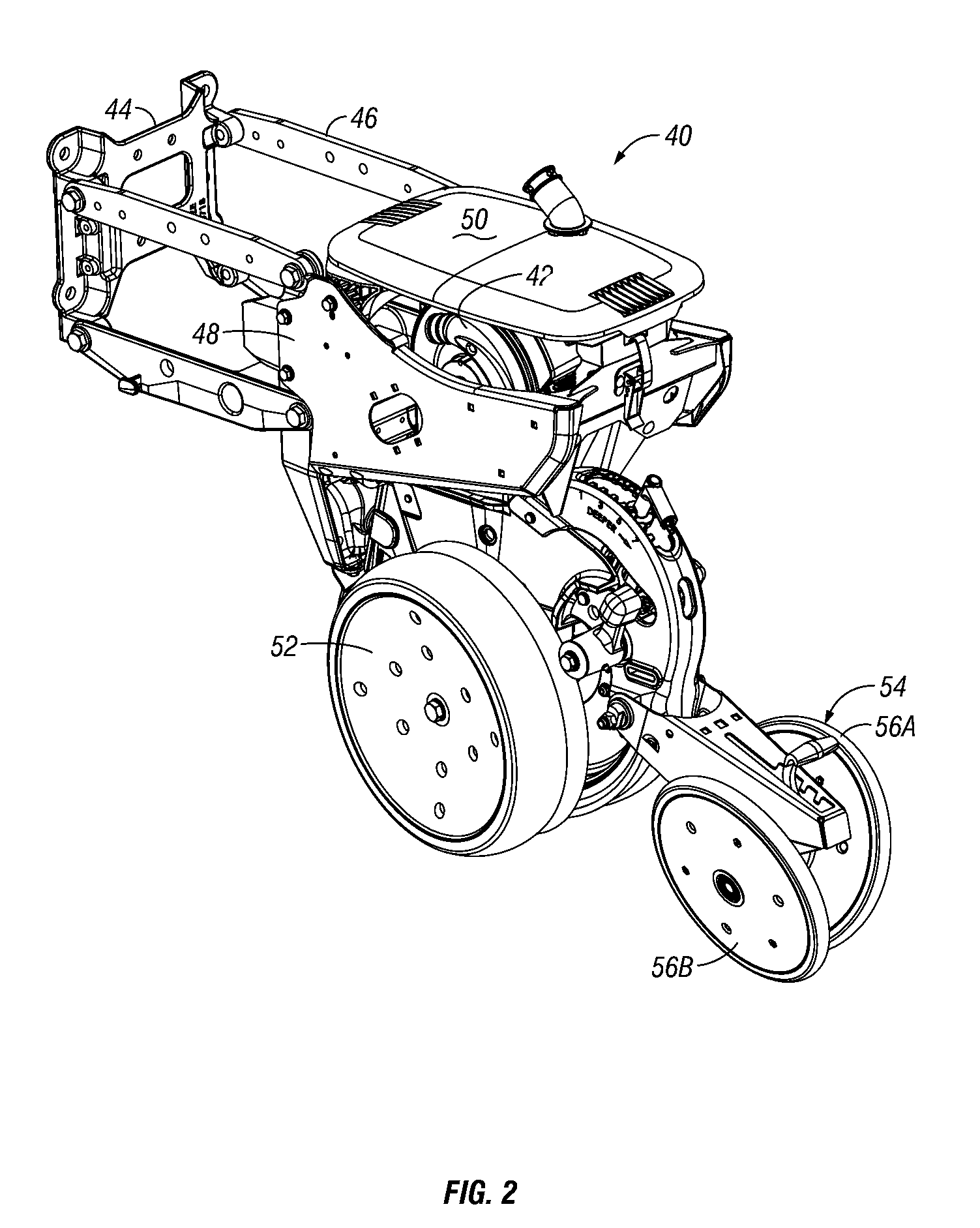
CROSS-REFERENCE TO RELATED APPLICATIONS[0001]This application claims priority under 35 U.S.C. §119 of a provisional application Ser. No. 61 / 975,047 filed Apr. 4, 2014, which is hereby incorporated by reference in its entirety.FIELD OF THE INVENTION[0002]The invention relates generally to agricultural implements for planting seed. More particular, but not exclusively, the invention relates to a row unit including a seed meter that includes an integrated pressure source, such as a vacuum source, to provide a pressure differential for adhering seed to a seed disc of the meter.BACKGROUND OF THE INVENTION[0003]An agricultural row crop planter is a machine built for precisely distributing seed into the ground. The row crop planter generally includes a horizontal toolbar fixed to a hitch assembly for towing behind a tractor. Row units are mounted to the toolbar. In different configurations, seed may be stored at individual hoppers on each row unit, or it may be maintained in a central hopp...

Claims


Application Information

Patent Timeline
IPC IPC(8): A01C7/04A01C7/20
CPCA01C7/20A01C7/046
Inventor HAHN, DUSTANWILHELMI, MATTHEW J.
Owner KINZE MFG INC
Learn More