Stationary gantry computed tomography systems and methods with distributed x-ray source arrays

a computed tomography and stationary gantry technology, applied in tomography, instruments, applications, etc., can solve the problems of large complex devices, inability to easily move, and large so as to achieve the effect of significantly reducing the window of time for optimal treatmen

Inactive Publication Date: 2015-10-08
THE UNIV OF NORTH CAROLINA AT CHAPEL HILL
View PDF7 Cites 31 Cited by
  • Summary
  • Abstract
  • Description
  • Claims
  • Application Information

AI Technical Summary

Problems solved by technology

Over 795,000 strokes occur a year, resulting in direct and indirect health care costs that exceed 41 billion dollars per year.
Current CT scanners are large complex devices that are not portable or readily mobile.
Unfortunately, the window of time for optimal treatment can be significantly reduced by the transit time to a location, hospital or medical facility equipped with a CT scanner.
Previous attempts at designing a non-rotating gantry CT, such as the Dynamic Spatial Reconstructor (DSR) and the electron-beam CT (EBCT), have been met with limited success.
The cost, size, complexity and maintenance related issues of the DSR and EBCT systems have generally been prohibitive.

Method used


Image

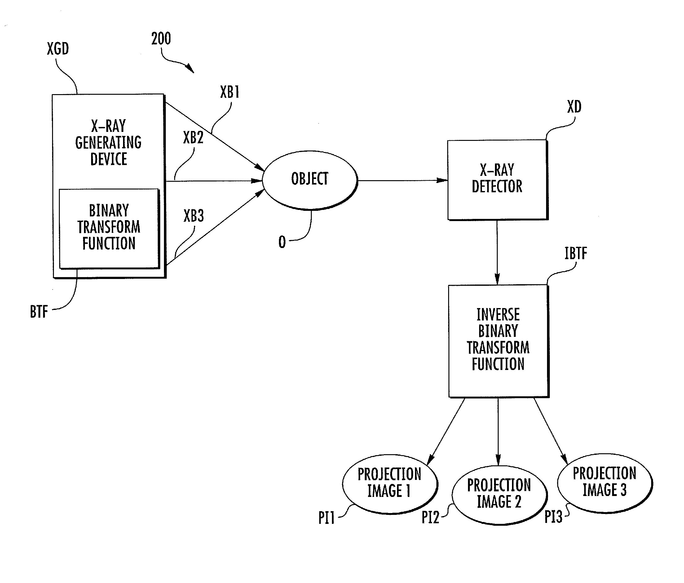
  • Stationary gantry computed tomography systems and methods with distributed x-ray source arrays
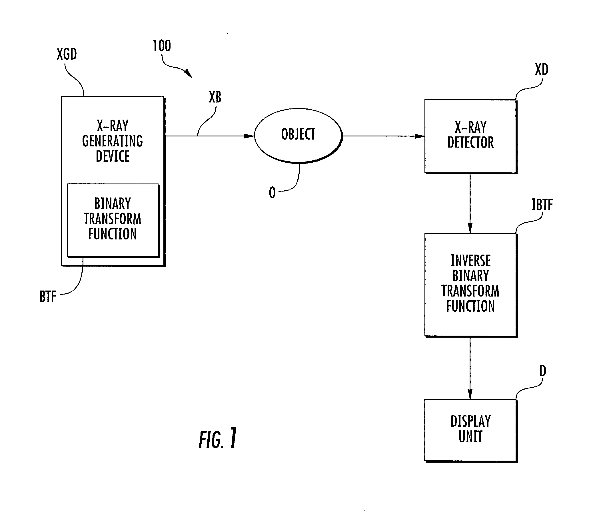
  • Stationary gantry computed tomography systems and methods with distributed x-ray source arrays
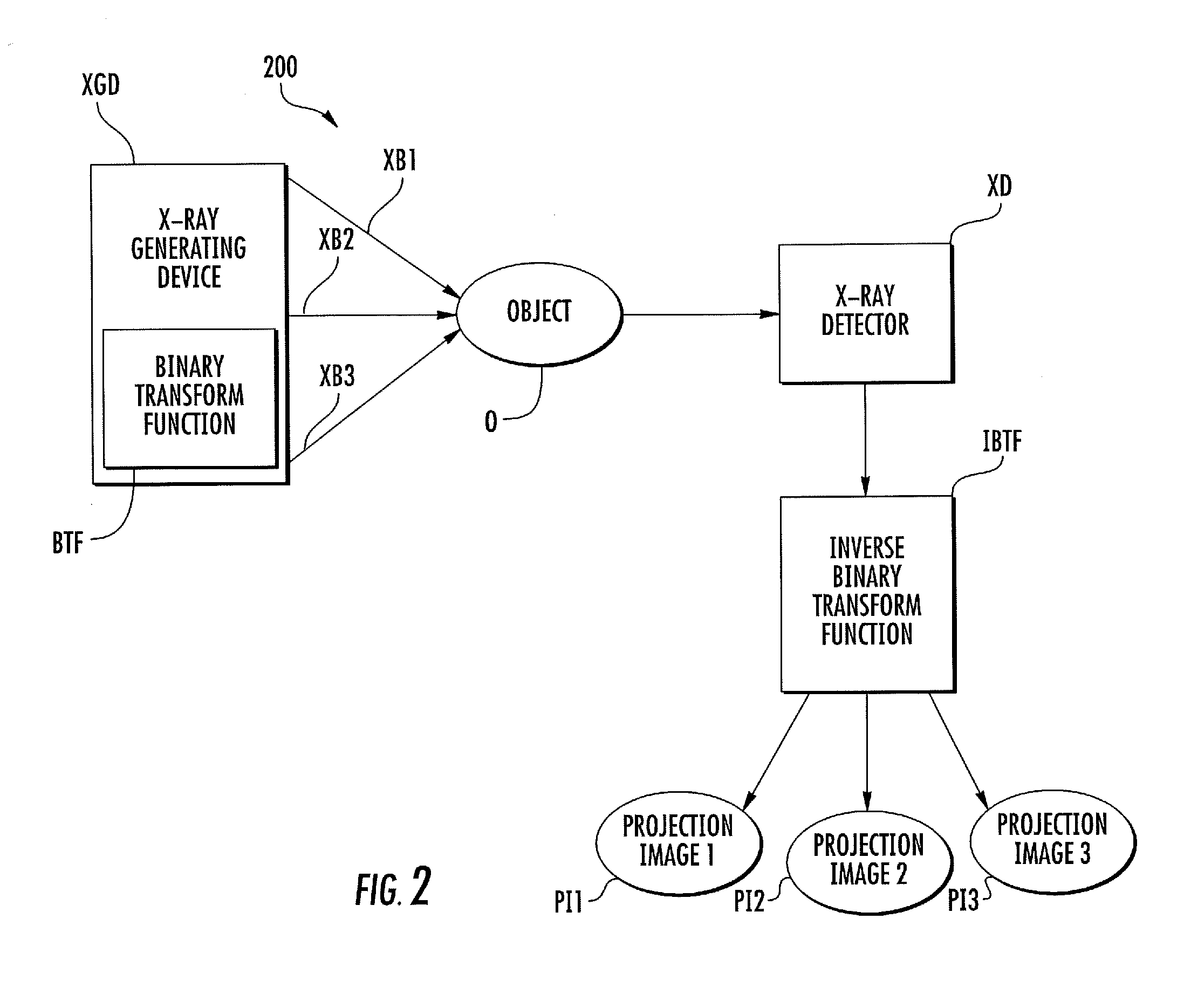
  • Stationary gantry computed tomography systems and methods with distributed x-ray source arrays

Examples


example 1

[0102]Preliminary data was acquired to demonstrate system feasibility with an existing CNT based linear x-ray source array and a low-resolution industrial linear detector. Z-axis coverage can then be increased by adding multiple linear detectors with resulting linearly scaled increase in speed, or by physical linear translation of the source detector combination. The translation over the axial field of view (FOV) of the head (approximately 23 cm) can be performed relatively inexpensively with high precision and speed with conventional mechanical components such as linear translation stages. Additional detectors could be added and used if there was a need for a significant increase in speed, such as for CT perfusion applications.

[0103]An image from the physical simulation of a potential geometry is illustrated in FIG. 14. Multiple passes from an existing 49 source linear array (spaced at 4 mm centers) were performed at 140 keV and 4.0 mAs exposure per slice. The scan configuration wa...


PUM


Abstract

Systems and methods for x-ray imaging are disclosed, particularly non-rotating, stationary gantry and mobile x-ray computed tomography systems and methods for imaging a subject, and particularly for imaging the head, spine, and neck of a subject. Compared to rotating-gantry computed tomography scanners, non-rotating stationary gantry x-ray computed tomography scanners are more mobile and transportable. Non-rotating stationary gantry x-ray computed tomography scanners can thus be used in mobile transport units and in-field applications.

Description

CROSS REFERENCE TO RELATED APPLICATION[0001]This application claims the benefit of and priority to U.S. Provisional Patent Application Ser. No. 61 / 684,575, filed Aug. 17, 2012, the disclosure of which is incorporated herein by reference in its entirety.GOVERNMENT INTEREST[0002]This invention was made with government support under Grant Nos. R01CA134598 and U54CA119343 awarded by The National Institutes of Health. The government has certain rights in the invention.TECHNICAL FIELD[0003]The subject matter disclosed herein relates generally to systems and methods for x-ray imaging. More particularly, the subject matter disclosed herein relates to non-rotating, stationary gantry and mobile x-ray computed tomography systems and methods for imaging a subject, and particularly for imaging the head, spine, and neck of a subject.BACKGROUND[0004]X-ray imaging is widely used in many areas including medical diagnostics and treatment, industrial inspection and testing, security screening and dete...

Claims


Application Information

Patent Timeline
Patent Type & Authority Applications(United States)
IPC IPC(8): A61B6/00A61B6/03
CPCA61B6/4435A61B6/4405A61B6/482A61B6/4014A61B6/032A61B6/025A61B6/4007A61B6/4241A61B6/487A61B6/541
Inventor LEE, YUEH Z.SHAN, JINGZHOU, OTTO Z.LU, JIANPING
Owner THE UNIV OF NORTH CAROLINA AT CHAPEL HILL
Why Eureka
Try Eureka