

Nanofluidic sorting system for gene synthesis and PCR reaction products
a technology of nano applied in the field of microfluidic and nucleic acid nanotechnology, can solve the problems of increasing gene length, reducing yield, and increasing gene length, and achieves the effects of increasing gene length, reducing yield, and high purity
- Summary
- Abstract
- Description
- Claims
- Application Information
AI Technical Summary
Benefits of technology
Problems solved by technology
Method used
Image

Examples
example 1
Device Fabrication
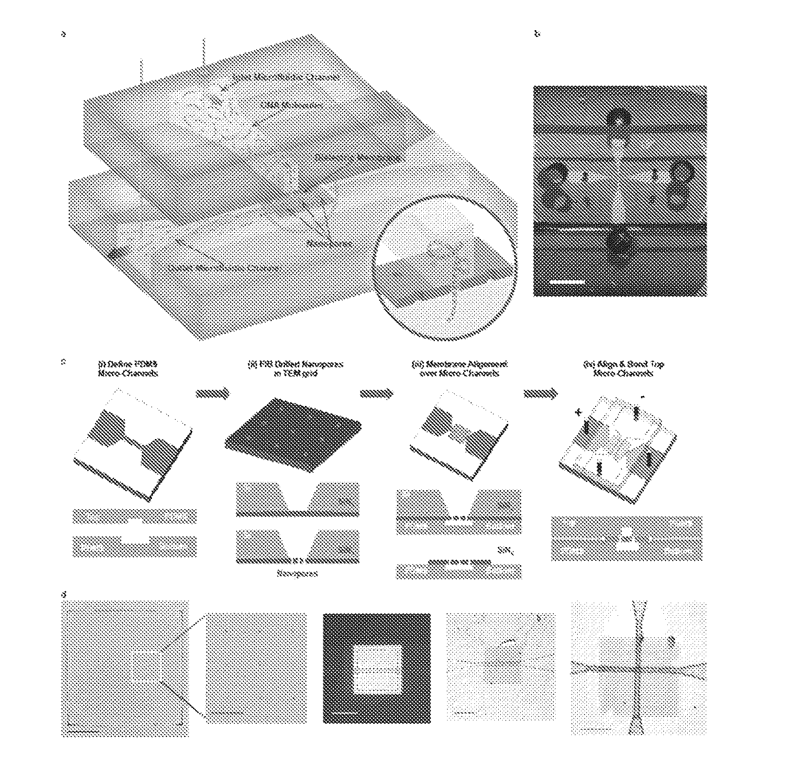
[0134]Photolithography (SU-8, Shipley) (e.g., soft lithography) was used to create a negative mold defining the microchannel system. Microchannel networks comprising larger access microchannels that taper into smaller microchannels (FIG. 1(c)(i)) were defined in polydimethylsiloxane (PDMS). The mold was chemically treated with 1H,1H,2H,2H-perflurododecyl trichlorosilane (Sigma Aldrich) for 6 hours prior to use. A 3:1 PDMS polymer:precursor ratio was poured over the SU-8 mold and cured for 8 hours at 80° C. The channels had widths of 8 μm and depths of 3 μm. The size of the smaller microchannels determined the membrane area exposed to the electrolyte solution, which may be tuned to, for example, less than 10 μm2.
[0135]Next, commercially available 3-mm diameter transmission electron microscopy (TEM) grids (Ted Pella / TEM windows) with 50 nm thick Low Pressure Chemical Vapor Deposition (LPCVD) SiNx membranes (SiNx) with free-standing areas of 100 μm×100 μm on a silicon...
example 2
[0162]In this example, a single nanopore and membrane were used to actively regulate molecular transport between adjoining microfluidic channels. FIGS. 12(a)-12(c) show a series of optical microscopy images where a fluorescent dye (Alexa 488) was introduced into the top microchannel. When no voltage bias was applied, dye remains in the top channel and does not actively transport through the nanopore (FIG. 12(a)). As a voltage bias was applied across the membrane, the dye electrophoretically moved into and through the nanopore to the lower microchannel (FIG. 12(b)). Moving the opposite bias from one end of the lower microchannel to the other end changed the direction of flow (FIG. 12(c)).
[0163]It is clear from this example that application of a voltage bias induces active transport of the dye through the nanopore. Furthermore, the direction of the molecular species through the microchannel is controlled by the placement of the electrode. Alternatively, pressure driven flow could be u...
example 3
[0164]Next, a device (FIG. 3(a)) containing three nanopores was produced. Each nanopore was connected to a common microchannel that acts as a ground (microchannel 0, FIG. 3(b) and a separate microchannel that acts as a source (microchannels 1-3, FIG. 3(b)). I-V curve measurements across each of the three microchannel intersections revealed resistances characteristic of single nanopores (FIG. 3(c)). As the applied voltage bias was moved from one microchannel to the next (FIGS. 3(d)-3(f)), transport of a fluorescent dye (Alexa 488) was directed through the corresponding nanopore and into the adjoining microchannel. Using a nanopore to act as a multi-level interconnect between microchannels on different planes enabled each channel to function as an isolated environment, whereby the nanopore electrically regulated transport between each compartment (Kuo, T. Z., et al. Anal. Chem. 2003, 75, 1861-1867, incorporated herein by reference). This feature opens up new possibilities in multiplex...
PUM
| Property | Measurement | Unit |
|---|---|---|
| Length | aaaaa | aaaaa |
| Length | aaaaa | aaaaa |
| Thickness | aaaaa | aaaaa |
Abstract
Description
Claims
Application Information