Energy transmission device and energy transmission system

a technology of energy transmission and energy transmission, which is applied in the direction of charging stations, electric vehicle charging technology, transportation and packaging, etc., can solve the problems of large leakage inductance, user danger, and unfavorable cable connection, and achieve the effect of saving costs

Inactive Publication Date: 2015-10-08
ROBERT BOSCH GMBH
View PDF3 Cites 3 Cited by
  • Summary
  • Abstract
  • Description
  • Claims
  • Application Information

AI Technical Summary

Benefits of technology

[0042]As a result, costs can be saved because the energy supply device is only provided in one of the energy transmission units.
[0043]In an alternative embodiment, the energy transmission device can also be installed only in the energy transmission unit of the motor vehicle which can be electrically driven. This thereby ensures that a solution which is independent of the charging station can be directly implemented in the motor vehicle. The motor vehicle equipped with the inventive

Problems solved by technology

Such a cable connection is however not very user friendly and furthermore represents a possible danger to the user because said user could come into contact with live parts if the plug connection or the cable is damaged.
The air gap causes large leakage inductances and a relatively poor coupling between the primary and the secondary coil.
The leakage inductances lead to high reactive currents in the system which do not contribute to the transmission of energy but produce ohmic losses.
For that reason, the effi

Method used


Image

  • Energy transmission device and energy transmission system
  • Energy transmission device and energy transmission system

Examples


Embodiment Construction

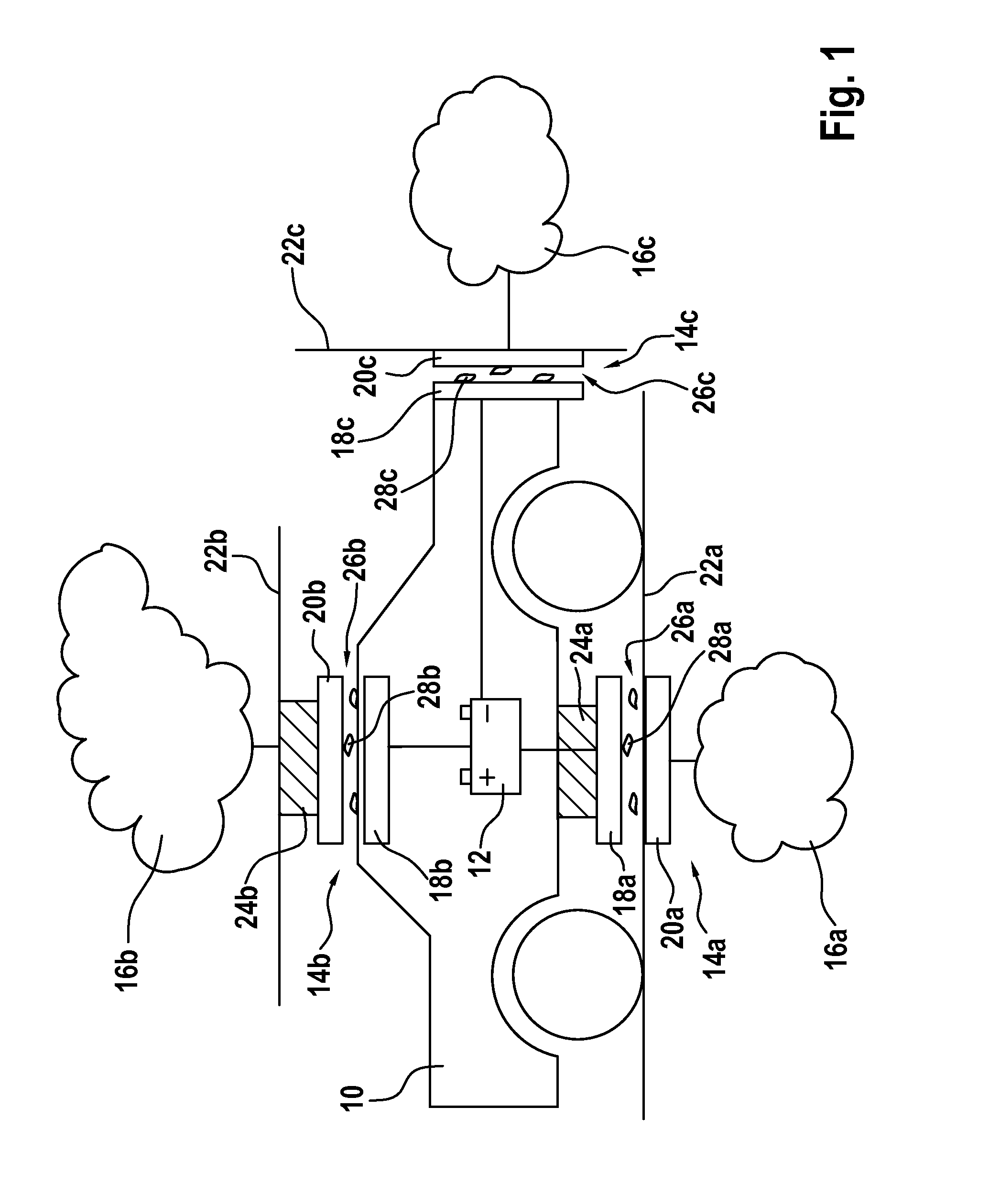
[0048]In FIG. 1, an electrically driven motor vehicle is schematically depicted and generally denoted with the reference numeral 10. The electrically driven vehicle 10 is, for example, an electrically powered vehicle 10 or a hybrid vehicle 10. In such electric or hybrid vehicles, electrical three-phase machines are typically used as the drive motor. The three-phase machine, which is not specified in FIG. 1, is usually supplied with electrical energy by a traction battery that is located on board the motor vehicle 10. After a certain operating time of the motor vehicle 10, the traction battery 12 has to be recharged with electrical energy. To this end, the traction battery 12 is electrically coupled via an energy transmission system 14 to the energy supply network 16. In FIG. 1, three alternative coupling options are shown which are identified by means of the corresponding energy transmission systems 14a, 14b, 14c and their associated energy supply networks 16a, 16b, 16c. As can be s...


PUM


Abstract

The invention relates to an energy transmission device (30) having a connection unit (32) for connecting an electrical energy source (16) or an electrical energy sink (12), a transmission member (34) which is electrically coupled to the connection unit (32) and which can be electrically coupled to a second transmission member (34) for transmitting electrical energy, and a cleaning unit (36) that is designed to introduce a cleaning medium (37) into a transmission path (26) between the first transmission member (34) and the second transmission member (34) in order to remove particles (28) from the transmission path (26).

Description

BACKGROUND OF THE INVENTION[0001]The present invention relates to an energy transmission device having a connection unit for connecting an electrical energy source or an electrical energy sink and a transmission member which is electrically coupled to the connection unit and can be electrically coupled to a second transmission member for transmitting electrical energy.[0002]The present invention further relates to an energy transmission system having a first energy transmission unit and a second energy transmission unit which can be electrically coupled to the first energy transmission unit in order to transmit electrical energy.[0003]In the field of motor vehicle drive technology, it is universally known how an electrical machine is used as the sole drive or jointly with a drive motor of a different type (hybrid drive). In such electric or hybrid vehicles, electrical machines are typically used as the driving motors which are supplied with electrical energy by an electrical energy ...

Claims


Application Information

Patent Timeline
IPC IPC(8): B60L11/18H02J5/00
CPCH02J5/005B60L11/182B60L53/124H01F38/14H02J50/10Y02T10/70Y02T10/7072Y02T90/14B60L53/12Y02T90/12
Inventor EYMANN, THOMASSCHUBERT, PETER
Owner ROBERT BOSCH GMBH
Why Eureka
Try Eureka