Hollow Drive Gear Reduction Mechanism

a technology of gear reduction mechanism and hollow drive, which is applied in the direction of belt/chain/gearing, manipulator, belt/chain/gearing, etc., can solve the problems of increased size of the whole drive gear reduction mechanism, increased assembly difficulty, and vibration, so as to reduce assembly cost, facilitate assembly, and reduce the effect of assembly cos

Active Publication Date: 2015-10-08
HIWIN TECH
View PDF7 Cites 9 Cited by
  • Summary
  • Abstract
  • Description
  • Claims
  • Application Information

AI Technical Summary

Benefits of technology

[0007]The primary objective of the present invention is to provide a hollow drive gear reduction mechanism which is simply structured, easy to assemble, and convenient for wiring.
[0013]The respective components of the present invention are assembled together in a coaxial manner, which makes assembly easier and reduces assembly cost. Furthermore, the design that the respective components of the present invention are all hollow structures, and the lateral aperture is formed on the hollow wave generator, makes wiring easier.

Problems solved by technology

However, this drive gear reduction is a solid structure, and almost provides no room for wiring.
However, the drive power source 25 is inserted deeply into the hollow base 21 and engaged with the reduction wheel 23 in a non-axial manner, and non-axial arrangement would not only increase the size of the whole drive gear reduction mechanism, but also make assembly more difficult.
Furthermore, since the drive power source 25 uses a small toothed drive wheel to engage with and drive the reduction wheel 23 which is much larger than the small toothed drive wheel, backlash will appear between the drive power source 25 and the reduction wheel 23, which consequently will cause motion loss, angular motion error, and vibration.
Hence, using toothed wheel as a drive wheel requires high machining and assembling accuracy, and increases manufacturing cost.

Method used


Image

  • Hollow Drive Gear Reduction Mechanism
  • Hollow Drive Gear Reduction Mechanism
  • Hollow Drive Gear Reduction Mechanism

Examples


Embodiment Construction

[0020]The present invention will be clearer from the following description when viewed together with the accompanying drawings, which show, for purpose of illustrations only, the preferred embodiment in accordance with the present invention.

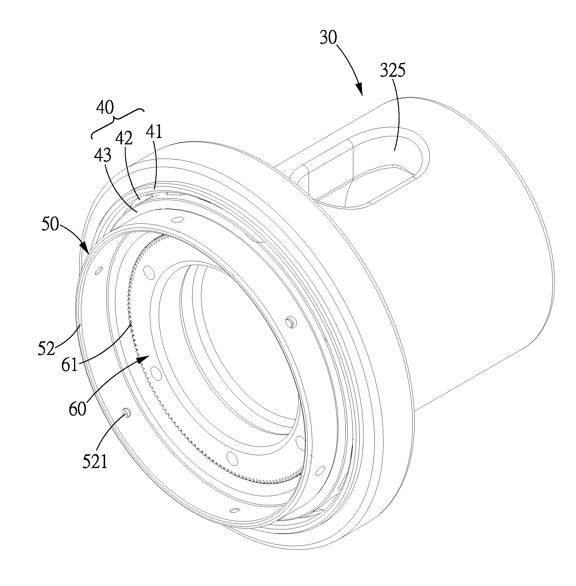
[0021]Referring to FIGS. 4-6, a hollow drive gear reduction mechanism in accordance with a preferred embodiment of the present invention is shown and comprises: a hollow wave generator 30, an annular flexible bearing 40, a flexible wheel 50, and a rigid wheel 60.

[0022]The hollow wave generator 30 has a wave generating section 31 formed at one end and a drive power input section 32 at another end thereof. The wave generating section 31 is formed with an elliptical recess 311 which is provided with an elliptical peripheral surface. The drive power input section 32 is formed with a drive power hole 321 which consists of a circular hole 322 and a spline groove 323.

[0023]The hollow wave generator 30 is further provided with a hollow passage 33 which i...


PUM


Abstract

A hollow drive gear reduction mechanism includes a hollow wave generator, an annular flexible bearing, a flexible wheel, and a rigid wheel. The annular flexible bearing is disposed in and driven to rotate by an elliptical recess of the wave generator. The flexible wheel includes an inner toothed section and is inserted in the annular flexible bearing and has an outer surface abutted against an inner surface of the inner ring, and the flexible wheel is driven to rotate by the annular flexible bearing. The rigid wheel includes a plurality of outer teeth which are different in number from the inner teeth of the flexible wheel, the rigid wheel is inserted in the flexible wheel, and a part of the outer teeth are meshed with the inner teeth. The respective components are hollow structures, and a lateral aperture is formed on the hollow wave generator.

Description

BACKGROUND OF THE INVENTION[0001]1. Field of the Invention[0002]The present invention relates to a drive gear, and more particularly to a hollow drive gear reduction mechanism.[0003]2. Description of the Prior Art[0004]FIG. 1 shows a conventional harmonic drive gear reduction 10 which comprises a wave generator 11, a flexible spline 12 sleeved onto the wave generator 11, and a rigid spline 13 sleeved onto the flexible spline 12. The wave generator 11 comprises an elliptical cam 111 and flexible bearing 112 sleeved on the elliptical cam 111. The elliptical cam 111 is connected to and driven to rotate by a power source. When the elliptical cam 111 rotates, it will push against and make the flexible bearing 112 and the flexible spline 12 deform, and as a result, the teeth at different parts of the deformed flexible spline 12 will be engaged with the teeth of corresponding part of the rigid spline 13, furthermore, the flexible spline 12 has less teeth than the rigid spline 13, so that a...

Claims


Application Information

Patent Timeline
Patent Type & Authority Applications(United States)
IPC IPC(8): F16H49/00
CPCF16H49/001Y10T74/19633F16H2049/003B25J19/0025
Inventor LIN, JIAN-AN
Owner HIWIN TECH
Why Eureka
Try Eureka